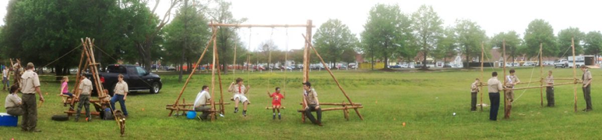

CAMP SEESAW VIDEO AND PHOTO MONTAGE

We were introduced to and adapted this project thanks to the great Pioneering Made Easy website. It was inspired by Fun With Ropes and Spars by John Thurman who, with his inimitable approach to providing pioneering challenges and robust Scouting activities, dubbed it the “Underwater See-Saw.” This version is a doable land approach that can be erected during a camping trip (where the materials are trailered in) or along side a Double A-frame Monkey Bridge as part of a simple, public demonstration of Scouting fun. Because of the size and weight of the materials required for its construction, it’s categorized under Involved Campsite Improvements, but when the smoke clears, what we’ve got here is a large campsite toy that’s relatively easy to build.  We’ll need:
- 4 10′ x 4″ leg spars
- 2 6′ x 3″ leg supports
- 2 2′ to 3′ x 3″ roller supports
- 3 2′ to 3′ x 2″ connectors
- 1 6′ x 4-1/2″ roller spar
- 1 10′ x 10″ x 2″ smooth plank
- 12 15′ x 1/4″ lashing ropes
- 4 20′ x 1/4″ lashing ropes for the roller supports
- 1 35’ x 1/4″ lashing rope for the plank
- 4 25′ x 3/8″ guylines
- 2 old tires
- 8 30″ pioneering stakes
Note: In building the see-saw, the premise is to space the A-frames, the roller supports and the two bottom connectors so that the 6′ roller spar can easily roll around, but can hardly move from side to side or up and down. Overall, this is a simple project though some precision will be required when positioning the plank at the right height so that riders don’t experience too much tilt. Like with any seesaw, care must be taken not to misuse the structure, but overall this camp seesaw is a tempting attraction and gets a lot of long-time play and attention. When built with care and guyed down securely, it can withstand the frequent use it invariably will get, even from heavier riders.

Build the A-frames. The first step is to prepare two matching A-frames using the leg spars and the 6’ leg support spars. You can use a Shear Lashing or a square lashing on top, and square lashings for the 6′ leg support spars. The main thing is to make sure that with both A-frames, the tops intersect the same distance from the tips and the legs spread apart an equal distance at the butt ends. 8″ up from the bottom and 8″ protruding from the legs is fine, and intersecting a foot from the tips works fine too.
Prepare to connect the A-frames. Stand the A-frames up so that the legs and support spars are parallel, about four and a half inches apart. Since the roller spar will eventually be rotating between the A-frames, the actual distance the A-frames are apart is determined by the diameter of the roller spar. Four Scouts should hold the A-frames upright and steady.

Lash on the roller support spars. Measure about 30″ up from the butt ends of all four legs. (For smaller, shorter riders, a lower height is definitely advised.) The height of the roller support spars will determine the angle of the board. Too steep an angle could easily make riding precarious. Begin connecting the two A-frames by lashing on the roller supports with tight square lashings. Lash them to the outside of the legs at a distance just a fraction wider than the diameter of the roller spar. For neatness, space them so the ends extend an equal distance out from the A-frame legs. Because these roller supports will be bearing the weight of the heavy roller spar, the plank, and the Scouts playing on the see-saw, when lashing them on with a Japanese Mark II Square Lashing, start the lashing by tying a Constrictor Knot around the leg to minimize any slippage.
Lash on the lower connectors. With the A-frames held steadily upright, temporarily lay the 6′ roller spar on top of the supports. Using the diameter of the 6′ roller spar as a measure, continue to connect the two A-frames by lashing on two connectors at a distance just above the roller spar, with tight square lashings. Again, for neatness, space them so the ends extend an equal distance out from the A-frame legs. Remove the roller and set it aside.
Lash on the top connector. Lash the last connector to one of the legs at the top of each A-frame, just below where the legs cross, with tight square lashings. If there is difficulty reaching the point on the legs where this connector needs to be lashed, carefully lay both parallel A- frames on their sides and then lash the connector in place. Again, for neatness, space the connector so the ends extend an equal distance out from the A-frame legs.

Make the Anchors. Build four 1-1 Anchors 45º out from each leg.
Attach the guylines. With a Roundturn with Two Half Hitches, or Rolling Hitches, tie on the 4 guylines, one each about two feet below the square lashings at the top of the A-frames. Connect each to its respective anchor.
Position the see-saw. Stand up and move the A-frames in the position you want the see-saw. Drive in each of the four pioneering stakes, fifteen feet away and 45 degrees out from where they’re tied to the legs of the A-frames. Connect a guyline to each using a Roundturn with Two Half Hitches or rope tackle.
Lash on the plank. Slide the roller spar on top of the roller supports. Lay the plank on top of the roller and using the 35′ lashing rope, lash the middle of the plank firmly in place with a square lashing.
Lay down the tires. On each side, at the point where the plank hits the ground, place a tire to cushion the impact and absorb the shock.
Some advisories and suggestions:
- Seesaws can be hazardous. Make sure there’s no horseplay. Just seated cooperation.
- When Riders take their places on the board, they should position themselves so their weight is balanced.
- Riders should never kick off from the ground forcefully springing their side skyward which can easily unbalance the other rider.
- Exiting the seesaw should only be done when both rider’s feet are on the ground.
- Adding ropes for handholds can be done in various places along the board by drilling holes about two inches from each edge and threading a short length of 3/8″ to 1/2″ braided nylon or polyester and tying a couple of figure eight stopper knots or tying the ends together on the underside of the board with a Water Knot.
- Making four indentation grooves in the plank where it will be square lashed to the roller bar will eliminate the plank slipping towards one or the other rider during use.