As an illustration to depict the description in the Outdoor Skills section of National Camping School, the following video portrays an example of a Scoutcraft Area in a long-term residential Scout camp:
Category: Involved Campsite Improvement
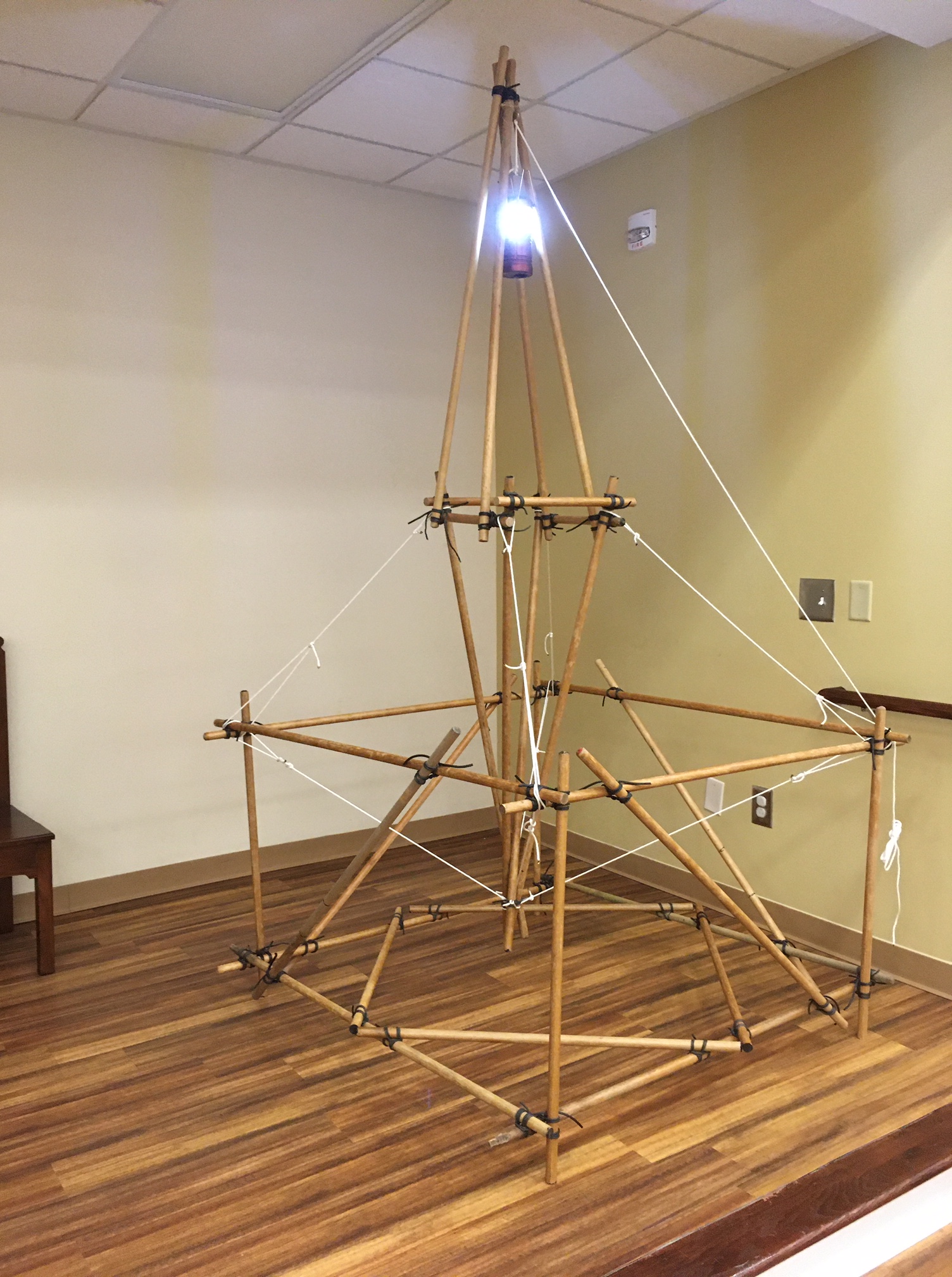
Campsite Beacon
![]()
This design was adapted from what John Sweet refers to as The Skylite in his booklet Pioneering in Town and Country. The main difference is the improvised framework for the two narrow quadpods is neither anchored or reliant on weighted supports, but instead is wide enough to allow the whole structure to be free-standing all by itself. With today’s lightweight LED lanterns, it’s easy to rig a halyard to raise and lower the lantern so it can be easily turned on and off. The novelty of floating the quadpods off the ground, like the Skylon “Floating” Flagpole adds and element of coolness to the structure as well as a little additional height for the beacon.

Double A-Frame Monkey Bridge as Presented in Scouting Magazine
Teach your Scouts how to build a monkey bridge
 Scouting founder Robert Baden-Powell believed every Scout should know how to build bridges. From designing the structure to gathering materials and putting it all together, bridge construction combines technology, teamwork and enthusiasm to complete a span that is memorable and useful.
A bridge on a hiking trail can be as simple as a log across a narrow gap. A more serious one relies on sturdier materials like rope and poles. A rope bridge Baden-Powell described in his 1908 manual, Scouting for Boys, is what today’s Scouts would call a monkey bridge.
Monkeying around
This is a classic pioneering project, and a variety of styles and instructions have been shared many times, from a 1965 Boys’ Life article penned by Scouting leader and author William “Green Bar Bill” Hillcourt to various editions of the Pioneering merit badge pamphlet.
If Scouts don’t have a stream or small gully to cross, they can build the bridge in a meadow or backyard. Follow safety rules, ensuring the foot rope is no higher than 6 feet off the ground and no longer than 25 feet between A-frames. Using a 50-foot rope, the maximum span between A-frames should be 20 feet, with the extra length being used for anchoring the bridge.
Before building any pioneering structure, it’s necessary to first acquire the wherewithal to experience success. The skills, along with the lashing ropes and poles required to build a monkey bridge using double A-frames for better stability, can be used time and again, for a variety of pioneering projects and troop meeting activities. Here’s how to build a monkey bridge.
Materials
- Eight 8-foot-by-4-inch A-frame legs
- Four 6-foot-by-3-inch ledgers
- 14 15-foot lashing ropes for square lashings (Use 1⁄4-inch manila for all lashing ropes.)
- Six steel rings or locking carabiners to join grommet and rope tackle
- Two 1⁄2-inch-by-10-foot polypropylene ropes for rope grommets
- Binder twine to create loops for tourniquets
- Six 10-foot lashing ropes for round lashings
- Two 1⁄2-inch-by-50-foot hand ropes

- One 1⁄2-inch- or 3⁄4-inch-by-50-foot foot rope
- Five to seven 8-foot lashing ropes for stringers
- 12 24- to 30-inch-by-21⁄2-inch pioneering stakes for two 3-2-1 anchors
- Two pieces of scrap burlap for saddles
1. Begin by building four identical A-frames with the 8-foot and 6-foot spars. Make sure the A-frames are all uniform in size when lashed together. Lash them together with three tight square lashings. You could also use shear lashings at the top of the A-frames.

2. Once you have four identical A-frames, it’s time to make two pairs of double A-frames. Stand up two A-frames so they overlap each other one-half their length (about 3 feet). Join the legs together where they intersect with a tight square lashing. Finally, lash the two 6-foot bottom ledgers together where they overlap with three tight round lashings. Do the same for the other double A-frame.

3. Drive the pioneering stakes into the ground first with three stakes together, then two, and then one. Use loops of binder twine and a small stick in between each set to form a tourniquet. Both 3-2-1 anchors should be installed about 10 feet from where the A-frames will be erected. Place a rope grommet around the front stakes, before applying the tourniquet joining the three front stakes to the middle two.
4. Position the double A-frames no more than 20 feet apart from each other. Lay the foot and hand ropes alongside the A-frames. Attach the stringer ropes to a hand rope with a clove hitch at 3- to 4-foot intervals along the hand rope. Make roundturns around the foot rope and tie the running ends of the stringer ropes to the other hand rope with a clove hitch.
5. Make two saddles by folding pieces of burlap, placing one above the square lashings in the middle of the double A-frames where they intersect. This is where the foot rope will rest.
6. With the double A-frames held in place on each side, place the foot rope over the saddles, and tie the hand ropes to the top of the A-frames with clove hitches on a bight.
7. About halfway between the anchor and the A-frames, tie a butterfly knot in the foot rope to form a fixed loop for a rope tackle (trucker’s hitch). With Scouts still holding the double A-frames in position, use the rope tackles to put strain on the foot rope. Next, pull the hand ropes tight and attach them to the anchors using rope tackle or roundturns with two half-hitches.
8. Once all the ropes are tightened, check the knots and lashings before crossing the bridge. Allow only one person on the bridge at a time.


Bridging the gap
Scouts can celebrate their bridge’s completion by crossing it and reflecting on how the project came together. What went well? What would they do differently next time? What roles did teamwork and leader-ship play in the project?
After it has served its purpose, the bridge can be dismantled: The ropes can be coiled and stored with the poles in a dry place, ready to bring out for the next pioneering project.
Helping Scouts realize they have the power to plan and construct big projects is a practical way to bridge the gap between the promise of Scouting adventure and fulfilling that promise in the field.
Robert Birkby is author of three editions of The Boy Scout Handbook, two editions of the BSA’s Fieldbook and the newest edition of the Conservation Handbook. Find him at robertbirkby.com
Special thanks to Larry Green
Brazilian Balance Track

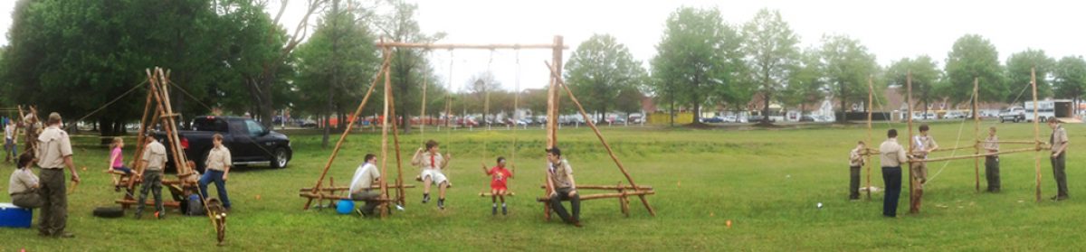
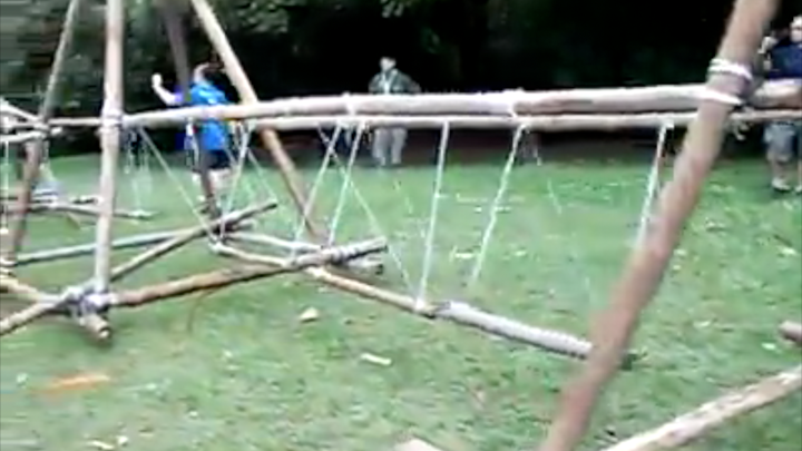
Pioneering projects can be built to serve a practical purpose, as in a bridge connecting two banks of a stream providing a shortcut to the dining hall, or simply for recreation as in a swing boat at a Scout Expo. The most desirable project constructed just for fun is the one that can get a lot of use. The more action it sees, the the more it can be considered a success. The Brazilian Balance Track, so dubbed because it came to our attention in a FaceBook post from the 88º GE / RJ Scout Group Atol das Rocas of Brazil as part of a training given by Chief Jorge Kuma Stotuka, is simply irresistible! Most everyone passing by is going to want to give it a go! For that matter, as revealed in the video, a group of Scouts will literally line up with individual Scouts waiting their turn to get on and see how easy or hard it is to make it from one end to the other.

Basically, the track consists of four quadpods connected by three ingenious, little challenges. Three of the quadpods also provide their own less daunting challenge. Variations in construction will be determined by the length of the spars connecting the quadpods, in other words, the degree each challenge is more or less demanding hinges on the distance between the quadpods and subsequently the amount of stepping, swinging, and negotiating required to traverse each section.
Here is the basic layout:
• Four 12-foot quadpods with four 8-foot crossbars about 6-inches from the butts, spaced about 10 feet apart
 • Inside 2nd quadpod: one 8-foot spar lashed to the center of the front and rear crossbars
• Inside 3rd quadpod: one 10-foot diagonal pole connecting the side crossbars
• Inside 4th quadpod: three evenly-spaced 8-foot spars lashed to the outside crossbars
• Between 1st and 2nd quadpod: seven 3-foot ladder rungs, suspended about 1 foot above the ground from two parallel, 12-foot handrails
• Between 2nd and 3rd quadpod: two 8-foot, lengthwise, swinging poles, one for each foot, suspended in two places about 1 foot above the ground from two 12-foot handrails
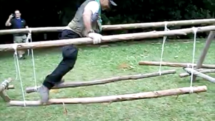
• Between 3rd and 4th quadpod: three, swinging, 3-foot rungs, each suspended in four places from two 12-foot handrails and lined up so they’re parallel to the handrails about 1 foot off the ground
Simple Camp Table

This small camp table can be comprised almost completely of Scout staves. It is 100% functional and provides a convenient raised surface for personal, patrol, or general use. It’s simple design makes it quick and easy to set up, and it is remarkably stable.
Make the table legs. Start by lashing together four Scout staves into two sets of shear legs with 6-foot manila lashing ropes. If you prefer, square lashings can be used instead of shear lashings. (In lieu of Scout staves, straight poles an inch or so in diameter are just fine.)
Lash on the table top supports. Next, with two square lashings, lash a 2-1/2-foot stick to connect each set of shear legs about 30 inches off the ground. (A Scout stave cut in two is ideal.) This will form two A-frames, one for each side of the table. Make sure each of these support sticks are lashed on straight and at the same distance from the bottom end of both sets of legs.
Securely hold up the A-frames. This is surely the best part. Find the midpoint of a 20-foot line. At about two feet away, tie a clove hitch at the top of one of the Scout staves of one of the A-frames. Repeat this process on the other side attaching the line with a clove hitch to one of the Scout staves of the other A-frame.
Secure each end of the 20-foot line to stakes driven into the ground on either side, about 5 feet away, so the line extends out evenly from each end of this table framework. You can use round turns with two half hitches, taut-line hitches, or rope tackles. Here’s the beauty of this configuration: you can manipulate the distance between the A-frames by adjusting the clove hitches, and provide optimum stability to the table by placing a good, reasonable strain on the line at each stake. It will stand up in an impressively rigid fashion.
Lash on the table top. Finally, lay 12 Scout staves, (or similar poles) side by side, on top of the 2-1/2-foot support sticks, and using binder twine, lash them on with floor lashings.

Sequential Programming: Monkey Bridge
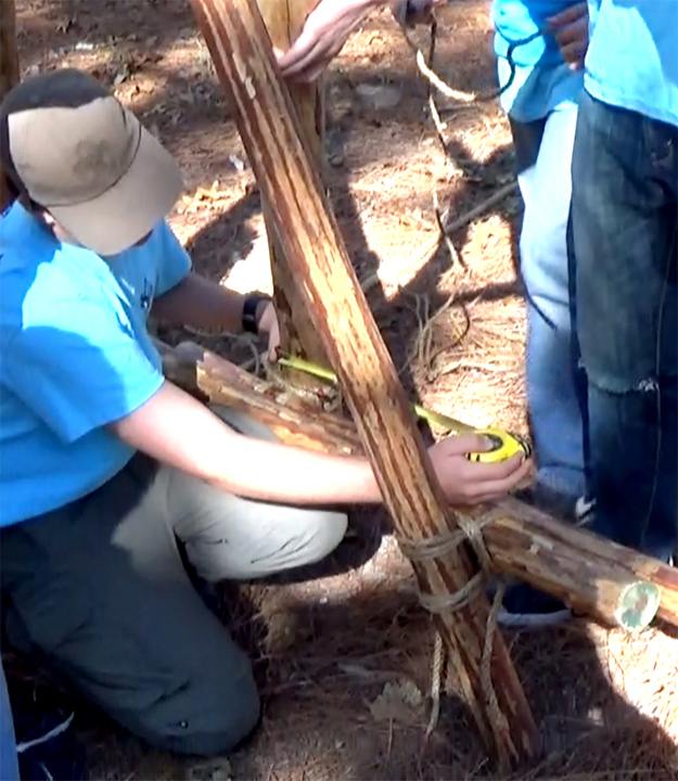
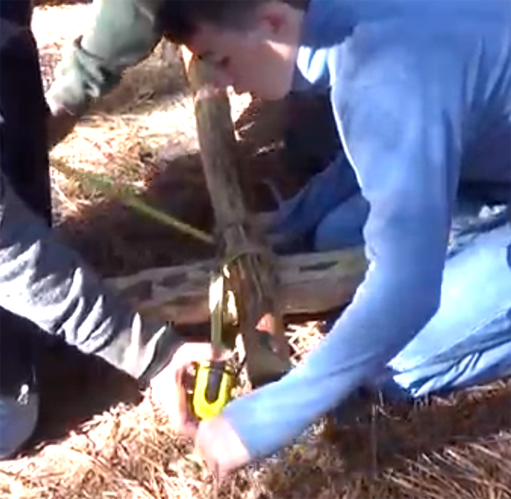
Troop 86 from Sumter, SC wanted to do a pioneering project and they selected the Double A-Frame Monkey Bridge. Great place to start, and a great way to illustrate sequential programming. What skills enter into the picture? A whole bunch! And with each step along the way, there’s an activity wherein each campcraft skill can be put into action, in a fun way, as reinforcement.
B.-P. wrote: “I am inclined to suggest to Scouters that in addition to the technical details of knotting, lashing, and anchorages, there is an educative value in Pioneering since it gives elementary training in stresses, mensuration, etc.” In addition to the “mensuration” skills that come into play when setting out the area for the bridge’s A-frames and anchors, a good deal of measuring takes place to assure the A-frames are as close to identical as possible, the pairs are joined together in similar fashion, an the spanner ropes are spread evenly. (Hand in hand with the building, Scouts do a lot of planning.)
 |
 |
—> What is Sequential Programming?
SEQUENTIALLY-PRESENTED SKILLS AND RELATED ACTIVITIES
Open-Ended Clove Hitch – How else would you want to secure the hand ropes to the A-frames? — How-to Video / Activity Video —
Using Half Hitches to tie a Clove Hitch – A simple process always makes it easy to tie a clove hitch and finish many types of lashings. Several are used to attach the spanner ropes. — How-to Video / Activity Video —
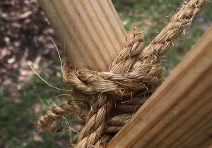
Round Lashing – Three or four can be used to join together the bottoms of the A-frames on each side. Round lashings can also be used to attach a flag pole(s) to an A-frame(s). — How-to Video / Activity Video —
Square Lashing – This project can use fourteen of them for both building the A-frames and then joining them together. — How-to Video / Activity Video —
3-2-1 Anchor – The skill is to carefully drive in the stakes at the proper angle and applying the tourniquets to join the groupings. — Explanatory Video —
Roundturn with Two Half Hitches – You can use this pioneering knot to attach the hand ropes to the anchors. — How-to Video / Activity Video —
Butterfly Knot and Rope Tackle – This configuration can be used to adjust the tension on the foot rope. — How-to Video 1, How-to Video 2 / Activity Video —
Skylon “Floating” Flagpole

A flagpole suspended off the ground by a series of lines, so that it appears to be floating, can be a really neat project. The structural principle has been referred to as tensegrity, and is based on using one half the lines to lift the pole off the ground, and the other half to give it stability, supporting it in a vertical position. On occasion, Scouts choose to use more than three upright support poles, but just like with a simple flagpole employing three supporting guylines, three upright poles provide the required balance needed to hold the pole up straight. The longer the support poles, the higher off the ground the flagpole can go.

There are many ways Scouts go about constructing a suspended flagpole. The following materials were used for this particular flag display:
- one 20-foot bamboo pole (flagpole)
- three 10-foot x 3-inch pine spars (upright support poles)
- nine pieces of rebar, sawed to 3 feet each
- six 50-foot lengths of 3/8-inch manila (guylines)
- three 3/8-inch double pulley blocks
- 50-foot length of 1/4-inch braided nylon (for the halyard) along with a couple of clips
- metal ring
- six pioneering stakes
- wooden mallet (for driving in the stakes)
- club hammer (for driving in the rebar)
- roll of friction tape
- lengths of 1/4-inch braided nylon cord
- binder twine
The following initial steps were taken for this particular flag display:
-

Double Pulley Block and Tackle Where the flagpole will be placed, 9 feet from the center of an equilateral triangle, three holes are made, 4 inches in diameter and 2 feet deep.
- A double pulley is securely tied to the top of each 10-foot support pole and a 50-foot guyline is reeved through each sheave.
- A 10-foot upright support pole is planted in each hole which is packed with excavated material. Three lengths of rebar are pounded in around each spar.
- A span of friction tape is applied to the areas of the 20-foot flagpole, where the lines will be tied (bamboo is slick)
- The metal ring is tied to the tip of the 20-foot pole and the halyard is threaded through.
- A 1-1 anchor is installed about 9 feet behind each 10-foot spar


The following rigging procedure was followed for this particular flag display:
- A tight jury mast knot (#1168 in The Ashley Book of Knots) is applied over the friction tape at the bottom and 4 feet from the top of the flagpole.
- The guylines from each upright support pole are tied to corresponding loops in the jury mast knots at the top and bottom of the flagpole with two half hitches, the tail of which is tightly seized to the standing part using binder twine with a West Country Round Lashing.
The following procedure was followed to raise and support this particular flag display:
-

1-1 Anchor When the flagpole is rigged and everything is in place, two or more Scouts lift up the pole in the center of the triangle, and hold it erect.
- One Scout mans each lifting guyline tied to the bottom of the pole. On signal, they all pull these lifting lines until the strain assumed by the Scouts holding the pole erect is replaced by the lower, lifting guylines. (Note: If the pole is taller or heavier, an additional Scout needs to man each guyline attached to the top, in order to stabilize the pole as it’s being held up, keeping it from tilting or falling. However, tension is only applied to offset any overt tilting.)
-

Top Stabilizing Guylines When the lifting guylines have taken up the strain to hold the flagpole at the desired height (about half the length of the upright support poles protruding from their holes), a butterfly knot is applied at the appropriate place and they are secured to the 1-1 anchor with a rope tackle.
- When the lower guylines are well secured, the upper, stabilizing guylines can be adjusted so that the flagpole is held up in a straight position. When the flagpole is even, the upper lines in turn are secured to their respective anchors with a rope tackle.


—> An alternate approach can be taken in which the flagpole is first stabilized in an upright position by the three upper guylines. These can then be temporarily secured, readying the flagpole to be raised off the ground. Once standing in a vertical position, upward force is applied to the flagpole by a Scout or Scouts holding on to the bottom and lifting, in conjunction with a simultaneous pulling on the bottom lines and a simultaneous easing off on the top lines. This lifting process is illustrated HERE.
14′ Climbing Tower at Scout Camp

Before the advent of BSA height restrictions on pioneering projects, the Scout-sized, 14′ Double Ladder Signal Tower was built by Scout units, Scout pioneering crews, and Pioneering Merit Badge classes on a regular basis.
Because it’s such a fine example of Scout Engineering, it has continued to be a feature in the Pioneering Areas of the national jamborees.
At this time, with the proper consideration and review from the Council Risk Enterprise Management Committee, in conjunction with the assurance the construction process will be carried out correctly and in accordance with pioneering safety guidelines, a structure like this that is taller than 6 feet can once again be built and climbed upon during Scouts BSA resident camp.
The photos of these Scouts were taken last week during their Pioneering Merit Badge class at summer camp.


Scout Swing

The design for this swing is not complicated, though it does present some logistical challenges. The main thing is, a working swing is going to get lots of play. Therefore, lashings need to be super tight, and the eight sturdy pioneering stakes that serve as anchors need to be driven solidly into the ground, perpendicular to and touching the six spars connecting the legs.
List of Materials
- six 3-1/2-inch x 12-foot spars for the legs
- one 4-inch x 12-foot spar for the crossbar
- six 3-inch x 6-foot connecting spars
- eight 3-foot pioneering stakes
- two 2-inch x 8-inch x 2-foot prepared swing seats
- four 20-foot x 1/2-inch swing ropes
- four steel rings
- four 6-foot x 5/8-inch ropes for Prusiks
- twenty 15-foot x 1/4-inch manila lashing ropes
- six 20-foot x 1/4-inch manila lashing ropes
- two single pulleys reeved with 20 feet of rope, with a small loop of rope tied to the top
- one eight-foot ladder
Though one might think this structure is built by making two simple tripods to support the crossbar, it’s MUCH better to make two A-frames, standing up vertically, supported by a third spar lashed to one leg of each A-frame, slanting down to the ground. The obvious reason is to give the crossbar maximum stability where it rests at the juncture of the two legs of each vertical A-frame.

Rig the swing seats. Attach two 20 foot swing ropes to the two swing seats, using a scaffold hitch rigged with a bowline. In order to accommodate the swing rope with the scaffold hitch, the swing seats should be prepared with impressions cut on each side, 2 inches long and 1/2 inch deep, beginning 1-1/2 inches from each end.
 Attach the rings to the crossbar. Using the 6-foot ropes, tie the steel rings to the crossbar with prusiks at intervals as per the measurements reflected in the diagram.
Prepare the A-Frames. Using two 12-foot spars and one 6-foot spar, with tight square lashings, lash together two identical A-frames making sure the tips of the legs cross the same distance from the top for each. Use a 20-foot rope where the tips of the legs intersect, and 15-foot ropes at the bottom. NOTE: Make sure the 6-foot connecting spars are lashed low enough to the bottom so later on there will be plenty of room to lash them to the pioneering stakes.
Add the oblique supporting legs. About a foot or so below the top lashing on the A-frames, lash on a third 12-foot spar to one leg of each A-frame, using 20-foot ropes. These spars will be angled down, extending out to support the A-frames in their vertical positions.
Connect the legs. Stand up the A-frames so they’re in a vertical position. Connect the 12-foot oblique supporting leg to the legs of each A-frame, using the remaining 6-foot spars and eight 15-foot ropes. Again, make sure they’re lashed low enough to the ground so later on there will be plenty of room to lash them to the pioneering stakes. (If you’ll be using the pulleys to lift up the 12-foot crossbar, loop one over the top of a leg, before standing up the A-frames.)
Position the two 3-legged subassemblies. Line up both support assemblies so they are facing one another on even ground and with the A-frames 10 feet apart.
Position the crossbar. Tie one end of each pulley rope to the ends of the crossbar, and have two Scouts carefully hoist the crossbar up to near the tops of the A-frames. They must carefully hold it in place. Position the ladder so that it’s even with one A-frame, and have a strong Scout climb about four to five feet up and lift the end into the crux of one A-frame. Repeat the process on the other side of the swing.
Lash on the crossbar. Making sure the rings are properly hanging down, and the crossbar is extending out approximately one foot from each side, one Scout will climb up and tightly lash the crossbar to one of the legs of each A-frame with a 20-foot rope.
Tie on the swings. One Scout will climb up and connect the swing ropes to the rings using a roundturn with two half hitches, making sure the swings hang evenly at the desired height.
Drive in and lash on the anchors. Four pioneering stakes are driven into the ground on each side—two spaced evenly and touching the bottom of each A-frame, and one against each connecting spar, hammered in near the oblique supporting leg. After these stakes are solidly in the ground, so they cannot jiggle, lash them to the connecting spars using 15-foot ropes.
Test the swing and make any adjustments as necessary.
Camp See-Saw

CAMP SEESAW VIDEO AND PHOTO MONTAGE

We were introduced to and adapted this project thanks to the great Pioneering Made Easy website. It was inspired by Fun With Ropes and Spars by John Thurman who, with his inimitable approach to providing pioneering challenges and robust Scouting activities, dubbed it the “Underwater See-Saw.” This version is a doable land approach that can be erected during a camping trip (where the materials are trailered in) or along side a Double A-frame Monkey Bridge as part of a simple, public demonstration of Scouting fun. Because of the size and weight of the materials required for its construction, it’s categorized under Involved Campsite Improvements, but when the smoke clears, what we’ve got here is a large campsite toy that’s relatively easy to build.  We’ll need:
- 4 10′ x 4″ leg spars
- 2 6′ x 3″ leg supports
- 2 2′ to 3′ x 3″ roller supports
- 3 2′ to 3′ x 2″ connectors
- 1 6′ x 4-1/2″ roller spar
- 1 10′ x 10″ x 2″ smooth plank
- 12 15′ x 1/4″ lashing ropes
- 4 20′ x 1/4″ lashing ropes for the roller supports
- 1 35’ x 1/4″ lashing rope for the plank
- 4 25′ x 3/8″ guylines
- 2 old tires
- 8 30″ pioneering stakes
Note: In building the see-saw, the premise is to space the A-frames, the roller supports and the two bottom connectors so that the 6′ roller spar can easily roll around, but can hardly move from side to side or up and down. Overall, this is a simple project though some precision will be required when positioning the plank at the right height so that riders don’t experience too much tilt. Like with any seesaw, care must be taken not to misuse the structure, but overall this camp seesaw is a tempting attraction and gets a lot of long-time play and attention. When built with care and guyed down securely, it can withstand the frequent use it invariably will get, even from heavier riders.

Build the A-frames. The first step is to prepare two matching A-frames using the leg spars and the 6’ leg support spars. You can use a Shear Lashing or a square lashing on top, and square lashings for the 6′ leg support spars. The main thing is to make sure that with both A-frames, the tops intersect the same distance from the tips and the legs spread apart an equal distance at the butt ends. 8″ up from the bottom and 8″ protruding from the legs is fine, and intersecting a foot from the tips works fine too.
Prepare to connect the A-frames. Stand the A-frames up so that the legs and support spars are parallel, about four and a half inches apart. Since the roller spar will eventually be rotating between the A-frames, the actual distance the A-frames are apart is determined by the diameter of the roller spar. Four Scouts should hold the A-frames upright and steady.

Lash on the roller support spars. Measure about 30″ up from the butt ends of all four legs. (For smaller, shorter riders, a lower height is definitely advised.) The height of the roller support spars will determine the angle of the board. Too steep an angle could easily make riding precarious. Begin connecting the two A-frames by lashing on the roller supports with tight square lashings. Lash them to the outside of the legs at a distance just a fraction wider than the diameter of the roller spar. For neatness, space them so the ends extend an equal distance out from the A-frame legs. Because these roller supports will be bearing the weight of the heavy roller spar, the plank, and the Scouts playing on the see-saw, when lashing them on with a Japanese Mark II Square Lashing, start the lashing by tying a Constrictor Knot around the leg to minimize any slippage.
Lash on the lower connectors. With the A-frames held steadily upright, temporarily lay the 6′ roller spar on top of the supports. Using the diameter of the 6′ roller spar as a measure, continue to connect the two A-frames by lashing on two connectors at a distance just above the roller spar, with tight square lashings. Again, for neatness, space them so the ends extend an equal distance out from the A-frame legs. Remove the roller and set it aside.
Lash on the top connector. Lash the last connector to one of the legs at the top of each A-frame, just below where the legs cross, with tight square lashings. If there is difficulty reaching the point on the legs where this connector needs to be lashed, carefully lay both parallel A- frames on their sides and then lash the connector in place. Again, for neatness, space the connector so the ends extend an equal distance out from the A-frame legs.

Make the Anchors. Build four 1-1 Anchors 45º out from each leg.
Attach the guylines. With a Roundturn with Two Half Hitches, or Rolling Hitches, tie on the 4 guylines, one each about two feet below the square lashings at the top of the A-frames. Connect each to its respective anchor.
Position the see-saw. Stand up and move the A-frames in the position you want the see-saw. Drive in each of the four pioneering stakes, fifteen feet away and 45 degrees out from where they’re tied to the legs of the A-frames. Connect a guyline to each using a Roundturn with Two Half Hitches or rope tackle.
Lash on the plank. Slide the roller spar on top of the roller supports. Lay the plank on top of the roller and using the 35′ lashing rope, lash the middle of the plank firmly in place with a square lashing.
Lay down the tires. On each side, at the point where the plank hits the ground, place a tire to cushion the impact and absorb the shock.
Some advisories and suggestions:
- Seesaws can be hazardous. Make sure there’s no horseplay. Just seated cooperation.
- When Riders take their places on the board, they should position themselves so their weight is balanced.
- Riders should never kick off from the ground forcefully springing their side skyward which can easily unbalance the other rider.
- Exiting the seesaw should only be done when both rider’s feet are on the ground.
- Adding ropes for handholds can be done in various places along the board by drilling holes about two inches from each edge and threading a short length of 3/8″ to 1/2″ braided nylon or polyester and tying a couple of figure eight stopper knots or tying the ends together on the underside of the board with a Water Knot.
- Making four indentation grooves in the plank where it will be square lashed to the roller bar will eliminate the plank slipping towards one or the other rider during use.
Large Camp Table
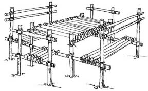
A design for this table had been on the drawing board for quite some time. Well, a day before the site was set up for a special Scout Campcraft program, it was decided to build one as a functional showpiece.

We sank four 6′ spars two feet into the ground for the main corners, and sank eight 4′ spars a foot into the ground for the rest of the upright supports. Between the corners we lashed two 10′ lateral spars, and for the two long benches and the sides of the table top, we used six-footers. The table top itself was comprised of 4′ platform spars, and the side seats, 3′ ladder rungs. Since the 10′ lateral spars were really too long, we compensated for the unexpected space between the 6′ bench spars and the ends of the ten-footers by dispensing with the back rests, and instead lashed on a flag at each corner.

What a piece of work! It stayed up for three weeks and repeatedly got plenty of heavy use on a daily basis. The Floor Lashings regularly needed adjusting, and served as a perfect location to pass on the Double Floor Lashing technique to program participants who applied it later to building rafts. The 4′ vertical uprights soon worked themselves to a slight wiggling state, but continued to furnish their necessary support. Also, during the three week period, due to the heavy adults who loved to seat themselves at this rather elaborate piece of camp furniture, occasionally various Square Lashings had to be tightened up as well. Nevertheless, with all the strain, rain, and wear, this version of the large camp table happily stayed intact.
Six Flag Banner Gateway
The concept for this gateway originated from the bamboo version placed at one end of Peschke Field at the 2013 national jamboree. Just like the name describes, this gateway flies a banner in the middle surrounded on each side by three flags. Each side is in the shape of a standing triangular prism. If the legs of each prism were far enough apart, symmetrical, and proficiently lashed, the structure could easily be self-standing. However in this instance, we’re using long, thin, yellow pine spars with unequal diameters and with an array of curves. So for stability, the gateway definitely needs to be guyed down at the front and back (outside) legs of each side!

To sport a ten foot banner and fly six 3 x 5-foot flags, a gateway like this conceivably can span as little as 20 to 24 feet. The dimensions of the above gateway are purposely larger, employing 8-foot spars to connect the legs, separated by two 14-foot center spars, so the width is closer to 30 feet. Since this project:
- is not designed for climbing
- relies on four guylines to keep it erect
- is fairly long and wide which can make hoisting a bit of a challenge
most of the spars can be thinner, lighter-weight pine. (Bamboo would be much better!) Naturally, the two triangular prisms should be bottom-heavy, so lash thicker, heavier connector spars at the bases of each side.
Here’s a list of materials:
- six 8-foot x 3-inch bottom leg connector spars
- twelve 8-foot x 2-inch middle and top leg connector spars
- two 14-foot x 2-1/2-inch center spars
- four 16-foot x 3-inch front and back (outside) leg spars
- two 18-foot x 3-inch middle leg spars
- eight rings or small pulleys
- eight 3-foot cords to attach rings or pulleys
- eight 40-foot x 1/4-inch braided nylon ropes for halyards
- eight lightweight carabiners for the flags and banner
- forty 15-foot x 1/4-inch manila lashing ropes
- four 6-foot straight spars for right and left front and rear flagpoles (optional)
- two 8-foot straight spars for right and left middle flagpoles (optional)
- twelve lashing ropes for round lashings to attach flagpoles to the tops of the legs (optional)
One key to building this gateway is to connect the middle and front leg of each prism shape with three leg connector spars, while both legs are lying flat on the ground. Once connected, the connector spars for the rear legs can be attached to the front and middle legs, after which the rear legs themselves can be held in position and lashed.

Another key to constructing the gateway is marking the positions on each leg, measuring up from the butt ends, where the connector spars will be lashed. The intent is to assure they’re evenly-spaced, parallel to one another and perpendicular to the legs.
After the center spars are lashed to the right and left middle legs, and when all the rings and halyards for the flags and banner are tied in the proper positions, the structure is hoisted from the back using the four guylines attached to the outside legs of both prisms (with rolling hitches or roundturns with two half hitches), and three hauling ropes attached to the top center spar with draw hitches. Refer to:“Hoisting the Tower”

The final step before securing the guylines to 1-1 anchors with rope tackles is to rotate each prism so that the front and back legs (outside) of each are positioned out at an equal distance from the middle legs.
Smaller Double Tripod Chippewa Kitchen

Basically, this is a mini version of the full-sized Double Tripod Chippewa Kitchen. Same procedure, just scaled down, and a perfect fit for one patrol. The only things different here are the dimensions:
- two 6-foot x 2-1/2 to 3-inch platform support spars
- six 6-foot x 2-inch tripod leg spars
- four 4-foot x 2-inch rear tripod braces
- two 4-foot x 2-1/2 to 3-inch front tripod braces (to support the platform support spars)
- fifteen to twenty 3-foot x 2-inch floor spars (depending on the size of the cooking surface required)
- sixteen 15-foot x 1/4-inch manila lashing ropes for square lashings (12-1/2′ lashing ropes work well if you have them.)
- two 20-foot x 1/4-inch manila lashing ropes for tripod lashings
- binder twine for floor lashing
- piece(s) of burlap or canvas to cover cooking platform (unless you’re using clay)
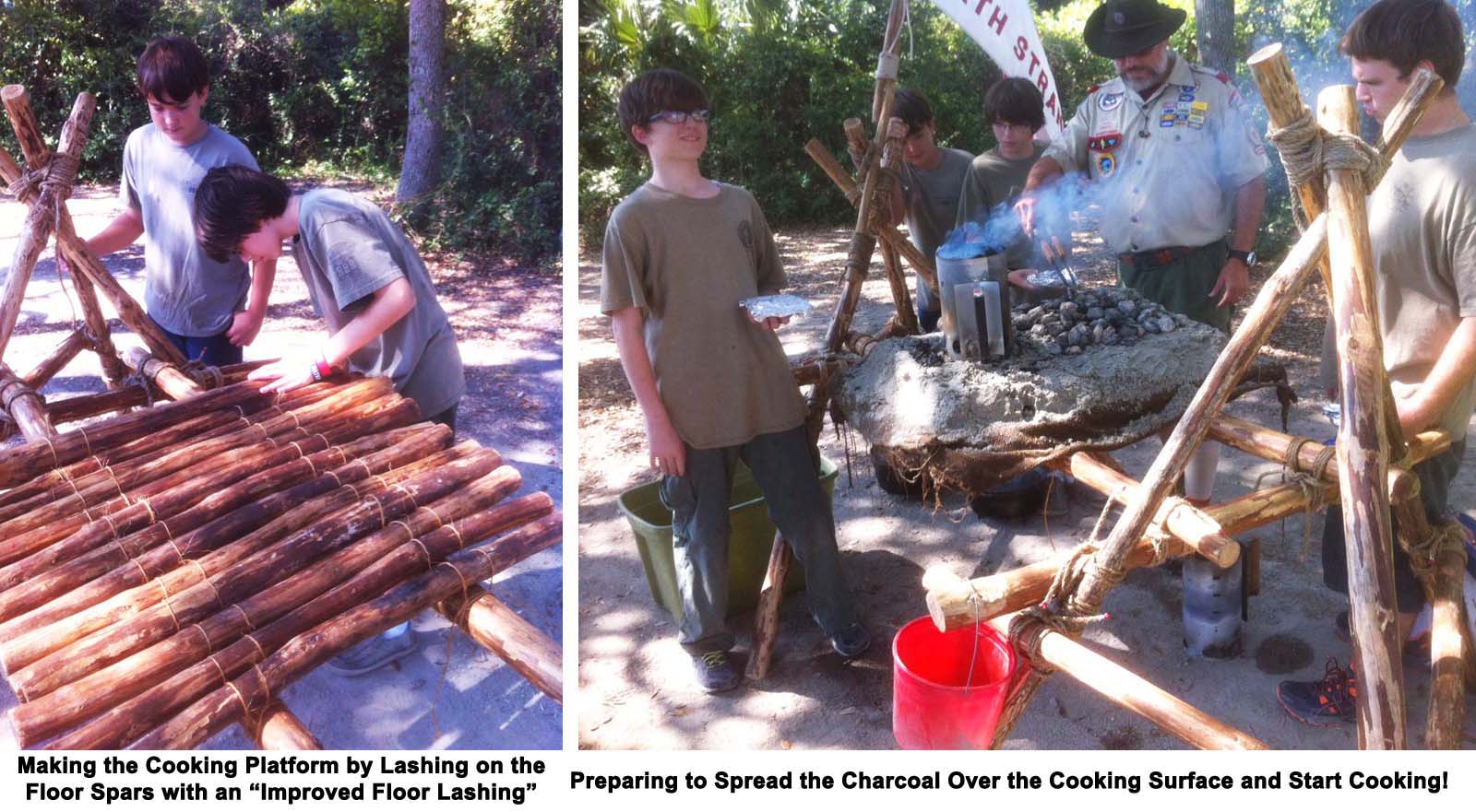
Note: When lashing on the tripod braces, position the two rear ones as low as possible. This way the thicker front one can be lashed on unencumbered, and also placed at the right height. When it comes to adding the two platform support spars you have a choice: lash them both on either the outside or on the inside of the front (outer) tripod legs. In these photos, they’re lashed on the inside.
For complete details, refer to the procedure outlined on the full Chippewa Kitchen post.
Catapults at the Jamboree

Before the Pioneering Area catapults were all completed and positioned in readiness for the thousands of jamboree participants who would be hiking up to Garden Ground Mountain, a little change of pace occurred which translated into a memorable moment. One morning during the building process, some soldiers passing though our area were attracted to the “giant” catapult with the heavy wooden counter weights, double throwing arm, and trebuchet-style swing extension. They were tempted to give it a try and what followed was a scene featuring modern day warriors coupled with ancient weaponry. (Click on the photo for a larger view.)
–
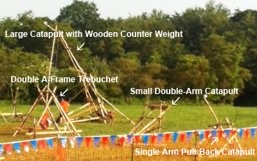 In addition to the “giant” catapult, three other catapult designs were featured up on Garden Ground Mountain in the pioneering area. Eventually, they were positioned on the far side of Peschke Field, facing a clear expanse of ground which was sectioned off to serve as a shooting area.
Periodically, to the amusement and awe of onlookers and those passing by, the 10′ Double A-Frame Trebuchet with a 200 pound counter weight would launch a large monkey fist in a high arc far down the length of the firing range.


The most excitement from the jamboree catapults was generated during Sunday’s Jambo-palooza festivities. A specially-built 8′ trebuchet was prepared, transported from Garden Ground, and set up at the stadium in Summit Center where it fired water balloons into throngs of Scouts gathered down range waiting to get doused. And, when it was apparent that a T-shirt was to be launched, the ensuing scrambling to catch it or grab it was over the top! (Click on the photo for a larger view.)
JAMBOREE PIONEERING AREA: MAIN PAGE

Jamboree Pioneering Area: Towers

Six towers were featured in Peschke Field. Four were for display and two were for climbing. Follow the links for photos and information about each:

