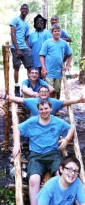
A Triumphant Success—posing on their Single A-Frame Bridge
In the Pioneering Area of the 2013 national jamboree, we put together a couple of Single A-Frame Bridge kits, so Scouts and Venturers could build this simple crossing bridge during their visit to Garden Ground Mountain. Each kit included:
Whenever a crew wanted to build a bridge, we provided an overview of the design and gave them a quick introduction to tying a rope tackle and the Japanese Mark II Square Lashing. What follows are some photo montages of the Single A-Frame bridges built from the kits during the jamboree. For larger and largest views, click on the photos once, and then once again:
Positioning their A-Frame in the ditch while preparing the guylines, and lashing the walkways to the transom.Lashing the transom to the legs and putting tension on a guyline.Positioning their A-Frame and hammering stakes in the corners of the walkways.Lashing on the transom to the legs.Lashing on the ledger and holding the A-Frame up while adjusting the height of the transom.The Shear Lashing at the top of the legs, and lashing the ledger at the bottom.Lashing the A-Frame legs with a Shear Lashing, and lashing on the transom.Carrying their A-Frame to the ditch and placing the walkways on the transom.Lashing on the transom and attaching the walkways.Tightly frapping a Square Lashing for the transom and working together to join the walkways to the A-Frame.Strop lashing the walkways to their A-Frame.
On occasion, a pair of Scouts wanted to build a bridge, and with persistence, and the help of staff or friendly Scouter, they were able to get it done.
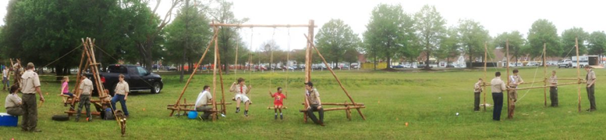
Two Single A-Frame Bridges in the Early Morning Fog on Garden Ground Mountain at the Summit Bechtel Reserve
The simplest of all crossing bridges is the Single A-Frame Bridge. The design was featured at the 2013 National Jamboree which afforded Scouts an opportunity to construct the bridge right on the spot.
The following text is by Adolph E. Peschke as presented in the 1998 printing of the 1993 edition of the Pioneering Merit Badge Pamphlet:
Building this bridge is quite simple because there are very few lashings needed for the center A-frame. The A-frame is a triangular shape that resists racking and provides strength for the structure.
A-frame. Start this project by determining the depth of the creek or ravine to be spanned. You have to add 8 feet to that measurement to get the total height of the legs for the A-frame. For example, to span a creek 4 feet deep, the legs of the A-frame should be about 12 feet or longer.
This total length allows for the distance from the butt ends of the A-frame legs up to the transom that supports the walkways. The transom should be about 1 foot higher than the banks of the creek. It also allows for the height from the walkways up to the tops of the legs to permit free passage for a person along the walkways.
Lay the A-frame subassembly out on the ground to check if the spars are long enough when lashed together for the two requirements mentioned above.
A-frame Legs. When you’ve determined the length of the spars for the legs of the A-frame, lash them together at the top with a shear lashing, not a diagonal lashing. This lashing should be made somewhat loose so that you can spread the spar legs apart to form the A-frame. As you spread the spar legs, the Shear Lashing will tighten. A little practice will show you how loose to make the shear lashing initially in order for it to be tight when the A-frame is formed.
View of A-frame and Attachment of Walkways
Ledger and transom. To complete the A-frame, use square lashings to lash the bottom ledger across the legs about 1 foot from the bottom of the legs. Then lash a transom spar to support the walkways at the proper height in relation to the banks of the creek.
Walkways. The two 10-foot walkway sections are made as separate subassemblies. (Refer to “Bridge Walkways.”)
Assembly. After the walkways are made, take them to the assembly site along with the A-frame. Place the A-frame in the center of the creek and heel in the legs about 4 to 6 inches deep. As the legs are being heeled in, level the transom to accept the walkways in a level position.
Single A-Frame Bridge
When the A-frame is upright and the transom is level, lash both underspars on the walkways to the transom with strop lashings at three points. Finally, lash the cross spars at the ends of the walkways to stakes on the banks of the creek with Strop Lashings.
For safety, it’s best to add a light 1/4-inch guyline from the top of the A-frame to both sides of the creek to prevent it from tipping over.
Lashing together a Trestle from Bamboo Spars (note the friction tape)
The following text is by Adolph E. Peschke as presented in the 1998 printing of the 1993 edition of the Pioneering Merit Badge Pamphlet:
A trestle is the basic component for building a bridge in a pioneering project. It is used to support the walkways.
The most basic form of a trestle is an H-frame. It consists of two legs, two ledgers, and two cross braces (see figure 125). When building a bridge, the top ledger is also called a transom. This is the part that supports the walkways.
To make an H-frame trestle, the two ledgers are lashed near the top and bottom of the legs and the cross braces are added, lashing them to the legs.
Figure 125
All of the lashing on the H-frame trestle is done with two types of lashings: a square lashing and a diagonal lashing. The ledgers are lashed to the legs with square lashings. Although it might not look like it, the cross braces are also lashed to the legs with square lashings, not a diagonal lashing. A diagonal lashing is used to lash the two cross braces together where they cross in the center.
When setting out to build an H-frame trestle, choose the two spars for legs first. These spars can be most any length, depending on the type and height of the structure you’re building.
To build a basic H-frame, lay the two legs on the ground with the two butt ends of the spars at the same end and even with each other. Then add the ledgers.
Ledgers. The ledgers are spars that are typically 2 to 2-1/2 inches in diameter. They are lashed to the legs with square lashings. Any of the three square lashings (shown in this pamphlet) can be used. The position of the ledgers on the legs will depend on the structure you’re building. There are a couple of general rules to keep in mind.
This Trestle is One of Several Subassemblies in a Larger Project
First, always keep the legs parallel and the butt ends of the legs even with each other as you’re lashing on the ledgers.* If you don’t, the trestle will stand crooked when you stand it up. As you add the ledgers, they should not stick out too far beyond the legs. You must leave enough room at the ends to tie the lashing, Any more will get in the way.
When using a Traditional Square Lashing or a Modified Square Lashing to tie the ledgers to the legs, be sure the starting clove hitch is placed on the leg so it’s beneath the ledger. When the clove hitch is below the ledger it will support it when the trestle is stood upright. As you tie the lashings, make sure they ar all very tight.
If you use a Japanese Mark II Square Lashing, you can start this lashing with a clove hitch in the middle of the rope to help support the ledger.
Cross braces. Next, the cross braces are added. The cross braces are spars that are usually 2 inches in diameter. They are lashed to the legs in a particular sequence.
First, flip the trestle over and work on the opposite side from the ledgers (see figure 125). Lash one cross brace to the back side of both legs. As mentioned before, use a square lashing (not a diagonal lashing) to attach the ends of the cross braces to the legs.
The second cross brace is added so that the bottom end is on the same side as both ends of the first cross brace. The other end is placed on the front side, the side with the ledgers (see figure 125). This is done so that the cross braces are standing slightly apart. There will be a gap where they cross at the center.
Trestle built with 5′ Scout Staves
Diagonal Lashing. After the ends of the ledgers and the cross braces are lashed to the legs, stand the trestle up on end. Adjust the trestle so that the legs are parallel. Also check to see that the top ledger is parallel to the ground. If it is not, lower the trestle, untie the lashing, and adjust it.
When the legs are parallel and the top ledger is parallel to the ground, you’re ready to tie the diagonal lashing to the cross braces while the trestle is standing upright. This lashing is very important to the strength of the trestle.
The diagonal lashing creates triangles that are important to stiffen the arrangement of the spars and to keep the trestle from racking. Look around at steel towers, bridges, or buildings being erected and you will see the triangle used in many places for the same reasons as we use it to build a trestle.
When the cross braces are lashed to the legs, there is a slight gap between them where they crossed at the center. A diagonal lashing is used here because it starts out with a timber hitch. The timber hitch pulls the cross braces tightly together. This adds strength to the whole trestle. You have to keep a strain on the lashing rope as you complete the diagonal lashing with three wraps in each direction around the X. Then make two frapping turns between the cross braces to pull the wraps tight. Finally finish by tying another clove hitch on one cross brace.
Once the possibility of racking has been taken care of with the diagonal lashing, the trestle’s vertical legs provide support for a large downward load. Since this is a downward force, also known as a shearing force, the legs don’t have to be very big. In fact, the overall shape of the trestle is an engineered structure that is able to support quite a bit of weight with rather small-diameter spars for legs.
* An exception is building a Single Lock Bridge when the top of one trestle has to fit between the legs of the other.
This simple crossing bridge uses only a single trestle and two walkways. The legs of the trestle are extended up above the walkway to provide a way to attach a handrail. The length of the spars listed for the walkways and trestle will be enough to build a bridge that will span a creek or ravine that’s up to 4 feet deep and 18 inches wide.
This project can be broken into three subassemblies: the trestle, the two walkways, and the four light spars for handrails.
Trestle. Begin by building the trestle. The legs for the trestle should be spars that are about 3 inches in diameter and 8 to 10 feet long. When choosing these spars, take into account the depth of the creek you’re crossing.
The distance from the base of the legs to the top ledger (transom) on the trestle should be about 1 foot higher than the level of the banks of the creek. This will allow the walkways to slant up. Then allow an additional 4 feet in height on the legs from the top ledger up to the top of the legs for attaching the handrail.
The top ledger of the trestle should be about 3″ in diameter since it also acts as the transom and carries all the weight of the walkways and the person using it. The bottom ledger can be smaller: a 2 inch diameter spar will work here.
Drawing 1: Trestle Heeled in with one walkway positioned.
The trestle is assembled with Square Lashings to hold the ledgers and the ends of the cross braces to the legs. The center of the cross braces is lashed together with a Diagonal Lashing.
Walkways. The two walkways are assembled as separate sub assemblies. (Refer to Bridge Walkways.) Be sure to make the cross spar at the end of the walkway long enough to attach to both the stakes and the handrails without getting in the passageway.
Assembly. To assemble the bridge, set the trestle in the center of the creek. Heel in the bottoms of the trestle legs by setting them in holes approximately 4 to 6 inches deep (see Drawing 1). This will prevent the trestle from shifting, and is also a way to level the transom spar as the trestle is set in place so that the walkways are level.
Next, put the walkways in position from both sides and lash the walkways’ underspars to the transom (top ledger) of the trestle. Then drive stakes at the other end of the walkways. Lash the ends of the cross spars on the walkways to the stakes.
Handrails. Finally, handrails are provided to help those crossing the bridge and also add strength to the structure of the bridge. When the handrails are added, they form triangles with the walkway and the trestle leg. These triangles produce a strong structure that prevents the bridge from racking. Lash the handrails to the top of the trestle legs and to the stakes with simple Strop Lashings (see Drawing 2).
Drawing 2: view of assembled bridge with handrails.
")