Using the 14′ Double Ladder Signal Tower as a point of reference, here are the plans for a very tall campsite gateway that stands out (and up) and serves as an impressive feat of Scout engineering. One of the perks included in this project is it provides an opportunity for new Scouts to experience hoisting a “boy-sized” structure replete with their own special colors e.g. their patrol flags.
Since this 14-foot structure isn’t climbed on, the spars can be considerably thinner in diameter. Bamboo is ideal. Lashing on those flags attached to each corner creates a spectacular effect and hence the name “4 Flag Tower!”
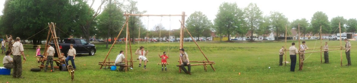
14′ Tower Gateway Schematic / Gateway to a Scout Expo Photo
Note: This design is not self-standing. Therefore, using it as a gateway at a camporee or Scout Expo with the necessary guylines requires an area wide and deep enough to accommodate a 16 x 16-foot space.
Scouts lash together a 4′ Side.
Materials Needed:
four 2-1/2 to 3-inch x 14-foot leg spars
six 2-inch x 8-foot X-brace spars
four 2-inch x 6-foot X-brace spars
four 2-inch x 6-foot support spars
six 2-inch x 4-foot leg spreader
forty-five 15-foot x 1/4-inch lashing ropes
four 25-foot guylines
eight 24-inch pioneering stakes
Assemble the 4-foot sides. Begin by laying out two pairs of 14-foot spars for the tower legs, side by side, 3 and 1/2 feet apart. Be sure the butt ends are even at the bottom so the tower will stand up straight.
NOTE:All lashings need to be very tight.
Diagram 1
Lash the legs together starting with a 4-foot bottom leg spreader about 6 inches up from the butt ends. Lash on a 4-foot middle leg spreader in the middle of the 14-foot legs (7 feet up), and a 4-foot top spreader about 3 inches from the top of the 14-foot legs.
When the legs are joined with the three 4-foot spreaders, lash on two 6-foot X-brace spars using square lashings to lash the ends to the legs, and a diagonal lashing where they cross, forming a trestle in the bottom half of the legs (see diagram 1). Three of the ends are lashed to the outside of the legs, and one on the inside, so that a slight gap is created where they cross. As the diagonal lashing begins, this gap will be cinched together with the timber hitch. Repeat the whole process with the other two 14-foot legs.
Diagram 2
Join the 4-foot sides. Turn both sides up horizontally, parallel to one another about 5 and 1/2 feet apart. Make sure the bottoms are even.
Lash on one of the 6-foot support spars directly above the 4-foot middle spreader (see diagram 2).
Lash another one of the 6-foot support spars directly under the 4-foot side spreader at the very top.
Lashing the X Braces with a Diagonal Lashing.
Now, lash on two of the 8-foot X brace spars diagonally between the two 6-foot supports using square lashings to lash the ends to the legs, and a diagonal lashing where they cross forming a trestle in the top part of the wide (6-foot) side (see diagram 2). Three of the ends are lashed to the outside of the legs, and one on the inside, so that a slight gap is created where they cross. As the diagonal lashing begins, this gap will be sprung together with the timber hitch.
Lash the other side. To make the lashings on the other side, you have to get the whole crew together to carefully lift and roll the tower over 180° so that it’s laying on the X-brace, and the other sides of the 4-foot sides are easier to get to.
Repeat the same procedure as before.
Scouts carefully lift the structure and rotatie it 180° to lash the other side.
Lash on the middle X-brace. This X-brace is what will keep the four sides from racking. Lash the two remaining 8-foot X brace spars diagonally across the legs just under the 4-foot middle leg spreader (see Tower Gateway Schematic on the top of this page). Use square lashings to lash them to the legs and a diagonal lashing where they cross. To accomplish this, some crew members will have to hold up the top of the tower so that there is better access to all four ends of the 8′ X brace spars.
Lash on the flags. If you want a flag or flags to fly from the top of the tower, lash the flagpole(s) to the top of each tower legs using a couple of tight round lashings.
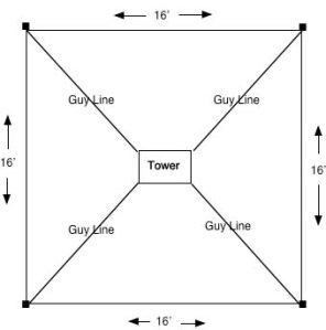
Tower Gateway Layout
Anchors and guylines. When all the lashings are done, move the tower to where it will be hoisted. Before actually hoisting the tower, lay out the position of the four legs on the ground. Then determine where the four anchors for the guylines will be placed to steady the legs of the tower.
Using the pioneering stakes, build four 1-1 anchors. Each should extend 16 feet, 45° out from the leg.
NOTE: Make sure the flags are unfurled before hoisting the tower.
Hoisting the tower. You’ll need a whole crew to do the hoisting. Get ready to hoist the tower by delegating the following:
One signal caller who tells the crew members when and how fast to pull on the ropes.
One safety officer who observes for all safety considerations and signs of trouble during the hoisting.
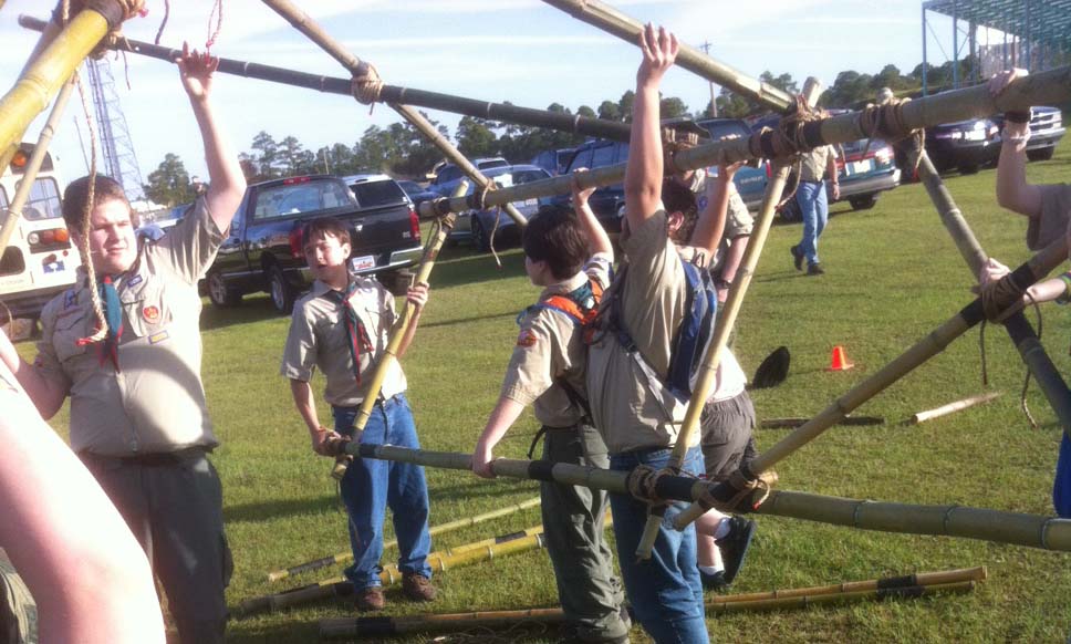
Four Scouts to serve as “Lifters” to lift the top 6′ support spar that’s on the ground. Their job is to first left and then push the tower up.
Two Scouts, one on each of the 2 guylines attached to the legs, to make sure the tower isn’t over pulled and topples over
Four “Pullers” who will use the two guylines as hoisting ropes to pull the tower until it is standing
We did it!
When everyone is in position, the signal caller should direct the Scouts on the hoisting ropes (the pullers) to hoist the tower into position, while the lifters start lifting. Care should be exercised not to over pull the tower.
As soon as the tower is standing, four Scouts should temporarily tie the guylines to the anchors using a roundturn with two half hitches.
Heeling the tower. If the tower is uneven, you can heel the the butt ends of the legs 4 to 6 inches deep as needed to make it more level.
Tighten the guylines. As soon as the tower is in position, go to each of the anchors and untie the Roundturn with Two Half Hitches and replace it with a rope tackle. Use the rope tackles to hold the tower steady, by gradually applying strain to each of the four guylines at the same time. Do this by tying a butterfly knot in each guyline about 6 to 8 feet from the anchor. Then wrap the running end of the guyline around the forward stake of the anchor and back through the loop in the butterfly knot. When rope tackles are tied to all four anchors, gradually tighten the lines. Apply enough strain to each of the guylines to hold the tower firm and in a vertical position. Then tie off the rope tackles and secure the running ends with half hitches.
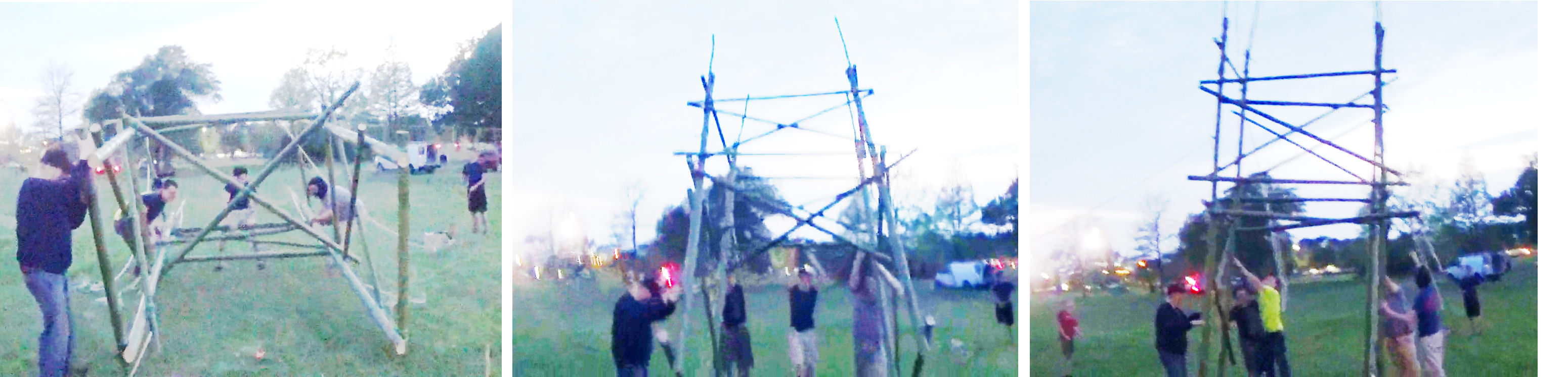
Hoisting a Larger Version: 17′ high x 8′ wide x 6′ deep
It’s a pretty safe to say most Scouts love to climb things. So, it makes sense that if a monkey bridge is combined with something to climb on, it will be even more fun. The challenge in constructing a project like this is to assure the structure can safely support not only the weight of those climbing on the platforms, but also the continual stress created by repeatedly crossing the rope bridge. Building this version of a double platform monkey bridge entails quite a few subassemblies and a procedure with many steps. Basically, with the materials listed, the ropes span a distance of 25 feet between two identical square platforms 4 feet wide and 8 feet high. At the front of each platform is an X-brace just under 5 feet high, providing a V for the foot rope. The hand ropes run through the junction where the X-braces intersect the top of the front legs, and then extend down joining the foot rope at a log-stake anchor 10 feet behind the back of each platform.
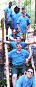
Bridge in operation during a Scout Expo
Here are the materials needed to construct the project:
eight 8-foot x 4-inch spars for platform legs
four 8-foot x 3-1/2-inch spars for X-braces
four 6-foot x 2-1/2-inch diagonal side braces
eight 4-foot x 3-inch spars for side base spreaders (4) and platform supports (4)
sixteen 4-foot x 2-inch spars for ladder rungs (10), handrails (4) and X-brace leg spreaders (2)
twenty-four 4-foot x 2-inch floor spars
two 4-foot x 4-inch log and stake anchor logs
sixteen 30-inch pioneering stakes for 2 log-stake anchors
sixteen large wooden stakes for the 8 guyline 1-1 anchors
sixteen small tourniquet stakes
two rope grommets with large O-rings
one 70-foot x 1/2 or 3/4-inch manila foot rope
two 70-foot x 1/2-inch manila hand ropes
eight 8-foot x 1/4-inch manila spanner ropes
thirty-six 15-foot x 1/4-inch manila lashing ropes
twenty-six 20-foot x 1/4-inch manila lashing ropes (for X-braces, base spreaders and platform supports)
eight 25-foot x 3/8-inch manila guylines
four 35-foot x 1/4-inch manila lashing ropes for floor spars
six burlap or canvas saddles (for the foot rope and hand ropes)
two large mallots
Binder twine
Tape Measure
Anchors are being built as sides are being connected.
Tips:
• Participants should be well-acquainted and experienced in the skills required for building this project.
• Select a project leader who will divide the participants into work groups, assign tasks, and oversee operations.
• Before proceeding, position the materials in proximity to the location where the project will be placed. It’s good to organize the materials by the tasks for which they’re needed.
• Depending upon how many Scouts are participating (will there be a small group of 6 Scouts, or a large group of 24), many of the subassembly steps needed to finish the project can be completed simultaneously. This division of labor can enormously streamline the project’s completion.
• If the opportunity presents itself, it can very helpful to initially lay out the hand and foot ropes, in conjunction with completing Task E, before proceeding with Tasks A & B.
• The following tasks can be completed at the same time:
Tasks A 1 & 2 / B 1 & 2 / Tasks D 1 & 2 and E
Task C 1 / Task C 2
Task F 1 & 2 / Task H 1 & 2
Tasks I & J / Tasks K, L & M
• If one task is taking longer to complete, workers from other groups can lend a hand and help finish it up so the next step can commence.
• Placing a 4-foot spar underneath the spars lying on the ground, in a strategic position, will raise the project sides up and make lashing much easier.
• There are 64 square lashings in this project and, for stability and safety, they must be tight! For speed and efficiency, the Japanese Mark II Square Lashing is highly recommended.
Schematic of Ladder Sides
TASK A – 1 & 2: Building the ladder sides of the platforms. 1) Lay out two 8-foot legs side by side. Space the spars apart so that the distance from the middle of each spar, at both the top and bottom ends, is 40 inches. Use a tape measure. Also, make sure the butt ends are at the bottom and absolutely even. Starting 6 inches up from the butt end, connect the legs by lashing on a 4-foot ladder rung directly above the 6 inch mark, with tight square lashings.
Using a tape measure, measure 5 feet up from the butt end of each leg, lash on another ladder rung, directly below, just touching, the 5-foot mark, ON THE OTHER SIDE (what will become the inside) of the legs. See the diagram on the right.
Right in the middle of these two ladder rungs, lash on another ladder rung, and then, between the middle ladder rung and the top and bottom ladder rungs, lash on two more. Use tight square lashings.
2) Repeat the whole process on two other 8-foot legs for the other platform.
Assembling an X-Brace Side
TASK B – 1 & 2: Building the X-brace sides of the platforms.
The premise for these sides is the X-braces have to cross each other just under 5 feet for the foot rope, and they have to intersect the tops of the legs equally on each side for the hand ropes. Because of the size of the spars involved, and the necessity for very secure connections that do not shift, use 20-foot lashing ropes and two Scouts for each X-brace square lashing.
1) Lay out two 8-foot legs side by side. Space the spars apart so that the distance from the middle of each spar, at both the top and bottom ends, is 40 inches. Use a tape measure. Also, make sure the butt ends are at the bottom and absolutely even. Starting 6 inches up from the butt end, connect the legs by lashing on a 4-foot ladder rung as a leg spreader, directly above the 6-inch mark, with tight square lashings.
Schematic of X-Brace Sides
With a tape measure, mark 56 inches up from the butt end of each leg.
Temporarily stretch a piece of binder twine over each 56-inch mark and tie it to each leg to help define where this intersecting line lies. It’s at the middle of this line where the X-braces need to cross so that the foot rope will extend just underneath the floor spars of the platform.
Lay out an 8-foot X-brace spar diagonally in such a way that the top end lays over one leg about 4 inches from the top of the leg, and extends out approximately 6 inches from the side. Angle the spar so that it will cross the middle of the intersecting line (56 inches up from the butt ends of the platform legs). Line up the bottom end of this X-brace so that it is positioned under the bottom of the opposite leg. Lash the spar in place with tight Square Lashings.
Lay out a second 8-foot X-brace spar on top of both legs so that it creates an X. Angle this spar so that it will cross the middle of the intersecting line (56 inches up from the butt ends of the platform legs). Make sure this spar also extends out approximately 6 inches from the side and that it intersects the leg at the same distance from the top as the X-brace on the other side. Lash this spar in place over both legs with a square lashing. It’s between the top of the front legs and the extension of the X-braces that the hand ropes will be supported.
Now, with a diagonal lashing, lash the middle of both 8-foot X-braces springing them together where they cross, using a 20-foot lashing rope.
2) Repeat the whole process with the two remaining 8-foot legs.
Schematic of Connecting Sides
TASK C – 1 & 2: Connecting the Ladder and X-brace sides. (If Task E has already been completed, before joining the ladder and X-brace sides, carry the two completed sides for each platform to the approximate location where they will eventually be positioned.)
1) Turn both a ladder side and an X-brace side up horizontally, parallel to one another. On the X-brace side, make sure the leg spreader and the X-brace spars are facing out. Space the legs apart so that the distance from the middle of each leg, at both the top and bottom ends, is 40 inches. Use a tape measure. Also, make sure the butt ends are absolutely even. With tight Square Lashings, join both sides by lashing a 4-foot side base spreader to the legs just below the bottom leg spreaders with a 20-foot lashing rope.
On the inside of the platform, using a 20-foot lashing rope, lash a 4-foot platform support to both legs so that the top edge comes up to 58 inches on both sides (directly under and as close as possible to the top ladder rung on the ladder side.). We will be laying the floor spars on top of this support.
Lash a 4-foot hand rail (same as ladder rung) to the top of both legs.
Lay a 6-foot diagonal side brace diagonally over both legs, between the base spreader and platform spreader, and lash in place using square lashings.
To join the other side, carefully lift and roll the platform over 180°, supporting the spars as much as possible, and repeat the above steps.
2) Repeat the whole process to join the ladder side and X-brace side of the other platform.
TASK D: Stand the platforms upright. With three Scouts lifting at the ground-level handrail, and two to three pulling on the other handrail, raise the platform to an upright position. If TASK E has been completed, we can proceed to Task G.
TASK E: Site preparation. Begin by stretching a length of binder twine along the center line of where the ropes will span. Drive a tent stake into the ground marking the center.
Working from the center, measure 12-1/2 feet toward each end and drive another tent stake to mark where the X-braces of each platform are to be placed. They should be 25 feet apart. Then with two other tent stakes, mark out another 14′ to where the anchors are to be built.
TASK F – 1 & 2: Build the anchors. The foot and hand ropes will be attached to anchors at both ends.
1 & 2) Build a log-and-stake anchor (also known as a log and picket holdfast), 14 feet from where the X-braces of each platform are to be placed. To make the log-and-stake anchors, place one of the 4-foot x 4-inch logs perpendicular to the pull of the line, 14 feet from where the X-brace side will be. Drive in a row of four pioneering stakes spaced evenly in front of the log, leaning them back at a 45° angle. Slip a rope grommet through an O-ring and then slip the ends of the grommet around the log (see diagram). Drive a second row of pioneering stakes 24 inches behind the front stakes. Then anchor the front pioneering stakes to the rear pioneering stakes with a tourniquet made of binder twine or rope using four tent stakes. After twisting the tourniquet tight, hammer the tent stake into the ground to keep it from loosening.
TASK G – 1 & 2: Position the platforms. All hands on deck! Move both upright platforms into position no more than 25 feet apart. Place them on the binder twine that marks the center line of the bridge, making sure the X-braces of each are facing each other 10 feet from the center mark.
Bridge in Operation at a Council-wide Scout Expo
TASK H – 1 & 2: Lash on the floor. Lay 4-inch floor spars on top of the platform supports so that the ends extend out evenly on each side. Using the Double Floor Lashing and the 35-foot lashing ropes, lash the floor securely in place.
TASK I – 1-8: Add anchors for platform guylines. For added stability, we’ll be adding four guylines to each platform. To start, measure 10 feet, 45° out from each leg and drive in a 1-1 anchor.
TASK J – 1-8: Secure the platforms. Attach one of the 25-foot x 3/8-inch guylines to each leg, directly above the floor spars, with a roundturn with two half hitches.
Extend the guyline down to the corresponding 1-1 anchor and attach it to the anchor with a rope tackle. Repeat this process at each leg.
TASK K: Foot rope. First place a piece of heavy canvas (called a “saddle”) in the top V formed by the X-braces. This will protect the foot rope and allow it to slide a little as needed.
If the foot and hand ropes are not already laid out during Task E, two Scouts will be needed to stretch the foot rope out, aligning the center of the rope with the center stake along the binder twine.
Next, lay the ends of the rope over the saddle in the V formed by the X-braces on each platform. Then, maintaining the rope’s center alignment between the platforms, extend the rope under the platforms, through the ladder sides and pulling it somewhat taut, thread the ends through the O-rings attached to the log-and-stake anchors. Tie these off temporarily with a roundturn with two half hitches.
TASK L: Hand ropes. Two Scouts will be needed to stretch the hand ropes out on either side of the foot rope, aligning the center of each with the center stake along the binder twine.
Climb the platforms and place saddles in the crotch between the X-brace extensions and the front legs. Maintaining the center alignment between the platforms, place one hand rope over its corresponding saddles. Then extend the rope down, crossing it over the outside of the top ladder rung, pull it taut, and thread the ends through the O-rings attached to the log-stake-anchors. Tie these off with a roundturn with two half hitches. Repeat the process for the other hand rope.
Good Show!
TASK M: Stringer ropes. Now add the stringer ropes that will go from the foot rope to the hand ropes. Start by tying the center of an 8-foot long stringer rope at the center of the foot rope, using a clove hitch. The stringer rope is tied around the foot rope so that both ends are 4 feet long. Add two more stringer ropes on both sides of the center stringer rope (so there are five stringer ropes in all), tying them about 4 feet apart.
Tie one end of each stringer rope to one of the hand ropes, again using a clove hitch. Then do the same with the other ends of the stringer ropes, attaching them to the other hand rope.
TASK N: Tighten the foot rope and hand ropes. Now you can put a strain on the foot rope. Undo the Roundturn with Two Half Hitches, and make a rope tackle on each end of the foot rope. Two Scouts will need to adjust the tension at each rope tackle so that the middle of the rope stays midway between the platforms.
As needed, adjust the tension of the hand ropes by tightening them at the anchors and retying the roundturn with two half hitches.
Final testing. With caution, one crew member can get on the bridge as all lashings, anchors, and knots are observed by the safety officer and all other crew members. Make adjustments as required.
Safe operation calls for only one Scout to be on the foot rope of the monkey bridge and up to two on either platform at a time.
Two Single A-Frame Bridges in the Early Morning Fog on Garden Ground Mountain at the Summit Bechtel Reserve
The simplest of all crossing bridges is the Single A-Frame Bridge. The design was featured at the 2013 National Jamboree which afforded Scouts an opportunity to construct the bridge right on the spot.
The following text is by Adolph E. Peschke as presented in the 1998 printing of the 1993 edition of the Pioneering Merit Badge Pamphlet:
Building this bridge is quite simple because there are very few lashings needed for the center A-frame. The A-frame is a triangular shape that resists racking and provides strength for the structure.
A-frame. Start this project by determining the depth of the creek or ravine to be spanned. You have to add 8 feet to that measurement to get the total height of the legs for the A-frame. For example, to span a creek 4 feet deep, the legs of the A-frame should be about 12 feet or longer.
This total length allows for the distance from the butt ends of the A-frame legs up to the transom that supports the walkways. The transom should be about 1 foot higher than the banks of the creek. It also allows for the height from the walkways up to the tops of the legs to permit free passage for a person along the walkways.
Lay the A-frame subassembly out on the ground to check if the spars are long enough when lashed together for the two requirements mentioned above.
A-frame Legs. When you’ve determined the length of the spars for the legs of the A-frame, lash them together at the top with a shear lashing, not a diagonal lashing. This lashing should be made somewhat loose so that you can spread the spar legs apart to form the A-frame. As you spread the spar legs, the Shear Lashing will tighten. A little practice will show you how loose to make the shear lashing initially in order for it to be tight when the A-frame is formed.
View of A-frame and Attachment of Walkways
Ledger and transom. To complete the A-frame, use square lashings to lash the bottom ledger across the legs about 1 foot from the bottom of the legs. Then lash a transom spar to support the walkways at the proper height in relation to the banks of the creek.
Walkways. The two 10-foot walkway sections are made as separate subassemblies. (Refer to “Bridge Walkways.”)
Assembly. After the walkways are made, take them to the assembly site along with the A-frame. Place the A-frame in the center of the creek and heel in the legs about 4 to 6 inches deep. As the legs are being heeled in, level the transom to accept the walkways in a level position.
Single A-Frame Bridge
When the A-frame is upright and the transom is level, lash both underspars on the walkways to the transom with strop lashings at three points. Finally, lash the cross spars at the ends of the walkways to stakes on the banks of the creek with Strop Lashings.
For safety, it’s best to add a light 1/4-inch guyline from the top of the A-frame to both sides of the creek to prevent it from tipping over.
Single Lock Bridge Photo Scanned from 1967 Field Book
The following text is by Adolph E. Peschke as presented in the 1998 printing of the 1993 edition of the Pioneering Merit Badge Pamphlet:
The single lock bridge shown here is a well-established and basic design. The list of spars shown for this project should build a bridge to span a creek or ravine approximately 4 feet deep and 18 feet from bank to bank.
Trestles. The bridge consists of two trestles and two walkways. Begin by building the two trestles as subassemblies. Adjust the length of the spars for the trestle so that when they are placed in the creek, as shown in Drawing 2, the tops of the ledgers will be about 1 foot above the level of the banks of the creek. This will give a comfortable slant to the walkways.
Drawing 1: Trestle Schematic
When constructing the two trestles, build only one trestle first. Then as the second trestle is being built, make sure that the legs are narrower at the top and fit between the legs of the first trestle (see Drawing 1).
Walkways. Next, the two walkways are constructed as subassemblies. Each walkway consists of two lateral spars. six cross spars, and two longer cross spars. One of these two longer cross spars is used as an underspar at the end of the walkway that is attached to the transom. The other longer cross spar is used to attach to the stakes. (Refer to Bridge Walkways.)
Drawing 2: Interlocking Trestles
Assembly. After building the trestles and walkways, take them to the assembly site (the creek or ravine). Place the trestles in the center of the creek so that the tops of the trestles are interlocked (see Drawing 2). Then lift a 3-inch diameter transom spar to fit on top of the interlocked trestle legs. Now, heel in the bases of the legs in holes 4 to 6 inches deep. As you’re heeling in the legs, level the transom spar so that the walkways don’t slant when they’re added.
Next, the two walkways are put into position (see Drawing 3). Lash the underspars on the walkways to the transom spar with Strop Lashings at three points. Finally, the cross spars at the ends of the walkways are lashed to the stakes.
By lashing the walkways to the transom spar and lashing the ends of the walkways to the stakes, you make a complete walkway unit that will prevent movement and provide a sturdy bridge deck.
This simple crossing bridge uses only a single trestle and two walkways. The legs of the trestle are extended up above the walkway to provide a way to attach a handrail. The length of the spars listed for the walkways and trestle will be enough to build a bridge that will span a creek or ravine that’s up to 4 feet deep and 18 inches wide.
This project can be broken into three subassemblies: the trestle, the two walkways, and the four light spars for handrails.
Trestle. Begin by building the trestle. The legs for the trestle should be spars that are about 3 inches in diameter and 8 to 10 feet long. When choosing these spars, take into account the depth of the creek you’re crossing.
The distance from the base of the legs to the top ledger (transom) on the trestle should be about 1 foot higher than the level of the banks of the creek. This will allow the walkways to slant up. Then allow an additional 4 feet in height on the legs from the top ledger up to the top of the legs for attaching the handrail.
The top ledger of the trestle should be about 3″ in diameter since it also acts as the transom and carries all the weight of the walkways and the person using it. The bottom ledger can be smaller: a 2 inch diameter spar will work here.
Drawing 1: Trestle Heeled in with one walkway positioned.
The trestle is assembled with Square Lashings to hold the ledgers and the ends of the cross braces to the legs. The center of the cross braces is lashed together with a Diagonal Lashing.
Walkways. The two walkways are assembled as separate sub assemblies. (Refer to Bridge Walkways.) Be sure to make the cross spar at the end of the walkway long enough to attach to both the stakes and the handrails without getting in the passageway.
Assembly. To assemble the bridge, set the trestle in the center of the creek. Heel in the bottoms of the trestle legs by setting them in holes approximately 4 to 6 inches deep (see Drawing 1). This will prevent the trestle from shifting, and is also a way to level the transom spar as the trestle is set in place so that the walkways are level.
Next, put the walkways in position from both sides and lash the walkways’ underspars to the transom (top ledger) of the trestle. Then drive stakes at the other end of the walkways. Lash the ends of the cross spars on the walkways to the stakes.
Handrails. Finally, handrails are provided to help those crossing the bridge and also add strength to the structure of the bridge. When the handrails are added, they form triangles with the walkway and the trestle leg. These triangles produce a strong structure that prevents the bridge from racking. Lash the handrails to the top of the trestle legs and to the stakes with simple Strop Lashings (see Drawing 2).
Drawing 2: view of assembled bridge with handrails.