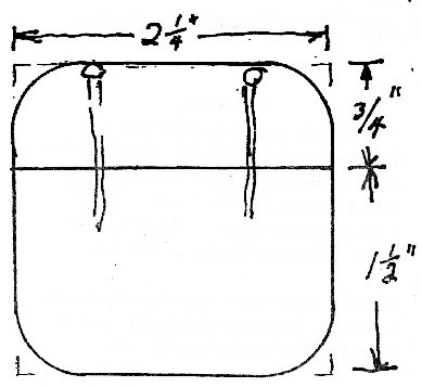
Getting that garbage bag off the ground has all kinds of advantages, but sometimes, you can’t hammer sticks into the ground to make the easy three stake holder. There might be any number of reasons. The ground’s got too many rocks. The ground is rock. You’re in a parking lot or on the sidewalk during a fundraiser. You’re indoors.
In these cases, to hold up a trash bag (when there is no trash can), you can simply lash three Scout Staves or similar poles into a tripod and lash on some short cross pieces to keep it stable. All that’s required is seven lashing ropes, one for a tripod lashing and six for square lashings. For the poles you need three 4 to 5-foot sticks for the tripod legs, and three short sticks for the tripod leg supports.
Note: The tripod lashing is tied below the middle of the longer sticks. The length that the sticks extend on top of the lashing will be determined by the size of the bag your holding. Also, to secure the bag on the holder, and too shorten or lengthen the amount the bag hangs, you can fold the top of the bag as much or as little as you like over the three upper leg extensions.
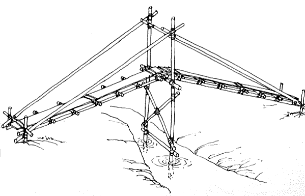
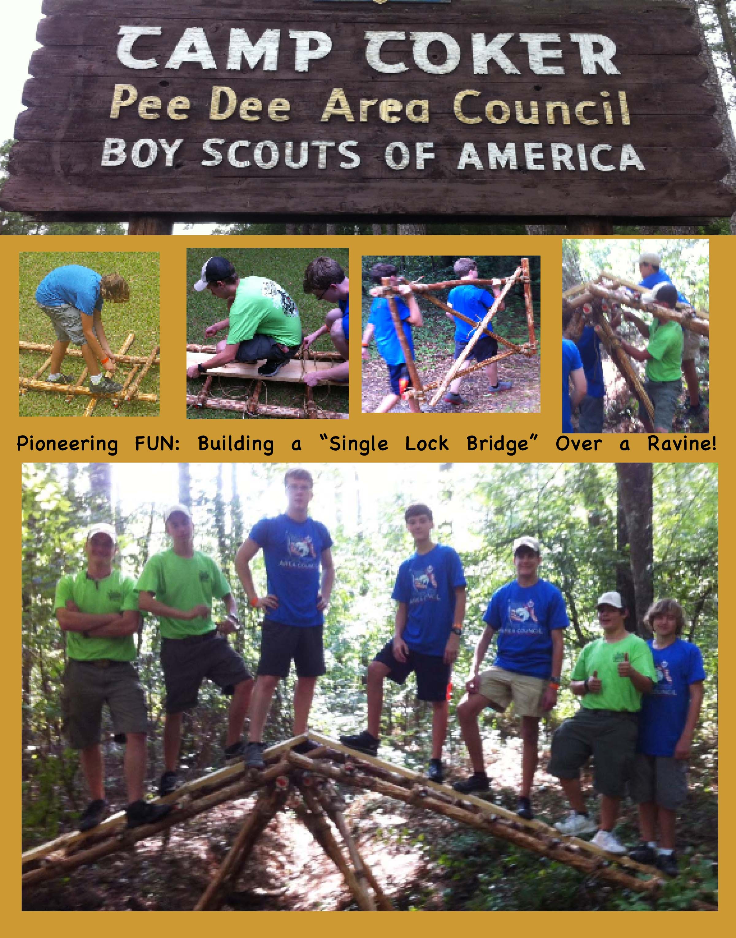
Single Lock Bridge Photo Scanned from 1967 Field Book
The following text is by Adolph E. Peschke as presented in the 1998 printing of the 1993 edition of the Pioneering Merit Badge Pamphlet:
The single lock bridge shown here is a well-established and basic design. The list of spars shown for this project should build a bridge to span a creek or ravine approximately 4 feet deep and 18 feet from bank to bank.
Trestles. The bridge consists of two trestles and two walkways. Begin by building the two trestles as subassemblies. Adjust the length of the spars for the trestle so that when they are placed in the creek, as shown in Drawing 2, the tops of the ledgers will be about 1 foot above the level of the banks of the creek. This will give a comfortable slant to the walkways.
Drawing 1: Trestle Schematic
When constructing the two trestles, build only one trestle first. Then as the second trestle is being built, make sure that the legs are narrower at the top and fit between the legs of the first trestle (see Drawing 1).
Walkways. Next, the two walkways are constructed as subassemblies. Each walkway consists of two lateral spars. six cross spars, and two longer cross spars. One of these two longer cross spars is used as an underspar at the end of the walkway that is attached to the transom. The other longer cross spar is used to attach to the stakes. (Refer to Bridge Walkways.)
Drawing 2: Interlocking Trestles
Assembly. After building the trestles and walkways, take them to the assembly site (the creek or ravine). Place the trestles in the center of the creek so that the tops of the trestles are interlocked (see Drawing 2). Then lift a 3-inch diameter transom spar to fit on top of the interlocked trestle legs. Now, heel in the bases of the legs in holes 4 to 6 inches deep. As you’re heeling in the legs, level the transom spar so that the walkways don’t slant when they’re added.
Next, the two walkways are put into position (see Drawing 3). Lash the underspars on the walkways to the transom spar with Strop Lashings at three points. Finally, the cross spars at the ends of the walkways are lashed to the stakes.
By lashing the walkways to the transom spar and lashing the ends of the walkways to the stakes, you make a complete walkway unit that will prevent movement and provide a sturdy bridge deck.
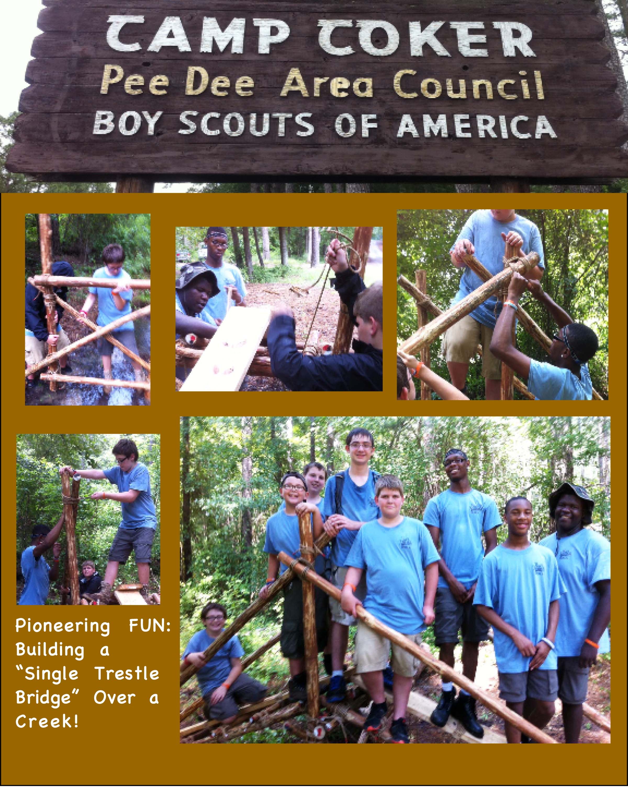
This simple crossing bridge uses only a single trestle and two walkways. The legs of the trestle are extended up above the walkway to provide a way to attach a handrail. The length of the spars listed for the walkways and trestle will be enough to build a bridge that will span a creek or ravine that’s up to 4 feet deep and 18 inches wide.
This project can be broken into three subassemblies: the trestle, the two walkways, and the four light spars for handrails.
Trestle. Begin by building the trestle. The legs for the trestle should be spars that are about 3 inches in diameter and 8 to 10 feet long. When choosing these spars, take into account the depth of the creek you’re crossing.
The distance from the base of the legs to the top ledger (transom) on the trestle should be about 1 foot higher than the level of the banks of the creek. This will allow the walkways to slant up. Then allow an additional 4 feet in height on the legs from the top ledger up to the top of the legs for attaching the handrail.
The top ledger of the trestle should be about 3″ in diameter since it also acts as the transom and carries all the weight of the walkways and the person using it. The bottom ledger can be smaller: a 2 inch diameter spar will work here.
Drawing 1: Trestle Heeled in with one walkway positioned.
The trestle is assembled with Square Lashings to hold the ledgers and the ends of the cross braces to the legs. The center of the cross braces is lashed together with a Diagonal Lashing.
Walkways. The two walkways are assembled as separate sub assemblies. (Refer to Bridge Walkways.) Be sure to make the cross spar at the end of the walkway long enough to attach to both the stakes and the handrails without getting in the passageway.
Assembly. To assemble the bridge, set the trestle in the center of the creek. Heel in the bottoms of the trestle legs by setting them in holes approximately 4 to 6 inches deep (see Drawing 1). This will prevent the trestle from shifting, and is also a way to level the transom spar as the trestle is set in place so that the walkways are level.
Next, put the walkways in position from both sides and lash the walkways’ underspars to the transom (top ledger) of the trestle. Then drive stakes at the other end of the walkways. Lash the ends of the cross spars on the walkways to the stakes.
Handrails. Finally, handrails are provided to help those crossing the bridge and also add strength to the structure of the bridge. When the handrails are added, they form triangles with the walkway and the trestle leg. These triangles produce a strong structure that prevents the bridge from racking. Lash the handrails to the top of the trestle legs and to the stakes with simple Strop Lashings (see Drawing 2).
Drawing 2: view of assembled bridge with handrails.
The Older Edition by Pioneering Legend, Adolph Peschke
Those of us who have experience providing a program of Scout Pioneering, and who are familiar with the edition of the Pioneering Merit Badge Pamphlet written by the legendary Adolph Peschke, will have no difficulty relating to why there are repeated references and allusions to the 1993, 1998 edition in this website, with its attention to detail, and when it comes to providing explanations that are helpful and comprehensive.
In the interest of accuracy, the recent 2006 edition has undergone many necessary revisions. There’s a website corresponding to the newest edition, and the post: What Pioneering Merit Badge SHOULD Be! is written from the author’s personal perspective.
In the interest of providing more and more Scouts with worthwhile pioneering experiences, and as an aid to those Scouters who are serious in making these experiences available to our youth, this website features specific text and drawings from Adolph Peschke’s edition.
What follows are links to posts containing the text and many of the drawings from the 1993, 1998 pamphlet:
Note: This website’s purpose is to share the joys and benefits of Pioneering and is not intended to serve as a direct aid in earning the Pioneering Merit Badge. But, for those interested, here is a link to the current requirements for the badge.
The following text is by Adolph E. Peschke as presented in the 1998 printing of the 1993 edition of the Pioneering Merit Badge Pamphlet:
PIONEERING PROJECTS
The craft of building with ropes and spars continues in remote areas throughout the world today. Scouts can apply the skills of knot tying and lashing to build pioneering structures that are needed to make living in camp a little more comfortable. Whether you build a simple gadget, or a bridge to provide a shortcut to the swimming pool, pioneering can be rewarding and fun.
The pioneering projects shown here, along with the suggested sizes and lengths of spars, are intended for building “boy-size” structures; that is, projects that can be built by boys of Boy Scout age.
You don’t have to build a huge tower to learn the skills and enjoy the fun of pioneering. These projects are designed so that you can build them in a few hours with a minimum of equipment and supplies. Yet, you will still learn how the basic pioneering skills of knot tying and lashing must work together with the design of a structure to produce a sound, safe pioneering project.
Building these projects will be much easier if you put together a pioneering kit first. The success of any project is directly related to the planning and preparation you put into the project from the beginning.
Here are some things to take into consideration before you build a pioneering project:
Decide on the type of project you want to build. Take into consideration the equipment, the number of people needed, and the time required to build it.
Check the site where the project is going to be built. Collect all the information that you will need when building the project. For example, are there any natural anchors for guylines? How wide and deep is the creek where a bridge is to be built?
Make a rough sketch of the project or work from an approved plan drawing. Along with the sketch, have a list of equipment that includes all the equipment you’ll need. You don’t want to start a project and later learn you need something you don’t have.
Select the necessary spars you’ll need for the project, making sure that you have enough spars with the proper butt diameter and length to build a safe project.
Determine the size and lengths of all the ropes needed for lashings, guylines, etc.
Before you start building, determine if the project can be divided into subassemblies for ease of lashing and erecting. Assign crew members and a crew leader to each of the sub assemblies, based on skill level and experience.
Go over the plans with all the crew members. Assign only one person to give signals when raising all or part of the structure.
As you’re building the project, frequently check the progress to make sure it is being done with safety in mind.
A word about the appearance of the project: Part of the skill in building with ropes and spars is to select the spars that are best suited to the structure. In some situations, the supply of spars might be limited.
It is not necessary for your project to be picture perfect, but rather that it is structurally sound. If one or two spars are a bit longer than required, that’s fine as long as the lashings are in the proper location for strength and the diameter of the spars will carry the load applied.
Try to avoid cutting off the ends of spars and ropes just to fit a certain project, especially if you’re working with spars from a pioneering kit. The next crew might want to build a different project and could use the spars and ropes at the original lengths.
The spars used for a pioneering project should have the bark removed for two reasons. Bark beetles and other boring insects can seriously decrease a spar’s strength, and inspection is easier with the bark removed. Also, if the project racks, the bark under the lashing can be loosened, which in turn makes the lashing loose and adds to the possibility of making the whole project wobbly and unsafe. (And, bark under a lashing can be rubbed off in the process of setting up a project.)
Note: Any pioneering structure that is to be a permanent camp improvement should not be left with only lashings. It needs to be bolted together for safety and maintenance.
Soon after the 1993 edition of the Pioneering Merit Badge Pamphlet was published, I ventured to contact its author with some questions. Happily, I was able to reach him at his home, and was treated to enthusiastic explanations regarding the projects our troop wanted to build. Mr. Peschke was always very generous with his time and had so much information to share, it always felt I was being given dollar answers for my little 10¢ questions.
Pioneering Legend, Adolph Peschke
The following text has been extracted from the Acknowledgments page of the Pioneering Merit Badge Pamphlet he authored: “Mr. Peschke has more than sixty years’ tenure in the St. Louis Area Council, and is a Wood Badge course director for more than 20 course staff experiences. He has designed thirty original “boy-size” pioneering projects. As a design engineer for five national Scout jamborees, he was responsible for the theme development, site layout, and staff training for the Action Center’s pioneering areas. He also developed the pioneering kit with its color-coded system to identify rope and spar lengths for building pioneering projects, and he has contributed to the BSA Fieldbook, Program Helps, and Boys’ Life and Scouting Magazines.”
Adolph Peschke, a most worthy recipient of the Boy Scouts of America’s Silver Antelope Award, passed away on November 23, 2012. He was 98. I had just spoken with him about two weeks before, during which time he was, as always, enthusiastic and emphatically informative. He will be missed, but his legacy will live on. Thank you Adolph! You have served, and continue to serve, as a most-helpful resource of valuable insight and information.
This signal tower went up on a camping trip in March of 2000 in a large grassy field. The operation took a little over two hours. PHASE 1: Before we started, a well-muscled sledge hammer crew, made up of Jason Hardee, Theodore Fontana, Cory Keibler, Kurt Lester, and Will Hall, took turns pounding in 24 three-foot pioneering stakes to make up the four “3-2-1” anchors we thought we needed to tie the tower down. (For years, we overlooked the fact all we really needed were 1-1 anchors.) PHASE 2: A crew assembled the 2 fourteen foot ladders. (All Scout campers tied at least one of the fifty Square Lashings required to put together the completed project.) PHASE 3: Another crew held the ladders in position while they were lashed together. Thanks to Jason for his Diagonal Lashings, and Theodore and Hiram for their help in lashing down the floor spars making up the platform. PHASE 4: The tower is hoisted with Scouts manning each corner guyline and the rope used to make sure the tower isn’t pulled too far before it’s secured. Thanks to Michael O’Neil who was in charge of tightening the guylines using the rope tackles at each of the anchors
The National Camp Accreditation Program (NCAP) Program Specific Standard PS-212 states: “Scout camp structures such as monkey bridges, obstacle courses, and pioneering towers are expected to meet safety standards in equipment and supervision comparable to COPE but are not subject to COPE standards, do not require COPE inspection, and do not require an on-site COPE Level II instructor. “VERIFICATION: If a project has participants elevated more than 6 feet above the ground, evidence of council enterprise risk management approval. This approval may be part of the general program design review in Standard PD-112.”
The following text is by Adolph E. Peschke as presented in the 1998 printing of the 1993 edition of the Pioneering Merit Badge Pamphlet:
This project solves the old problem of wanting to build a signal tower when there aren’t enough big spars to do the job. The double ladder tower requires four 14-foot spars and several smaller spars, but not nearly the amount needed for a four-leg signal tower. It also cuts down the number of lashings required.
This tower is not free standing. It requires the use of guylines to hold it steady. Review the sections on anchors and rope tackle if this is your first encounter with guylines.
Assemble the ladders. This project begins with building two ladders: a climbing ladder and a supporting ladder. Lay out two pairs of spars on the ground for the legs of the ladders. Be sure the butt ends are even at the bottom so that the tower will stand up straight. Before you begin any lashing, mark the positions where the spars that will hold the top platform are to be lashed onto the legs. This is about 4 feet from the top ends of the legs.
To make the climbing ladder, lash ten rungs on one pair of legs at about 1-foot intervals. The top rung should be lashed on where you marked the position of the platform, 4 feet from the top. Also the top handrail is lashed on to complete the climbing ladder.
To make the supporting ladder, lash three spars on the other set of legs to serve as the bottom, center, and top spreaders. The top spreader should be lashed at the point you marked for the platform, 4 feet from the top. Then lash on the top handrail, as on the climbing ladder.
Lash the ladders together. Now you have to join the two ladders to form the tower. Turn the two ladders up on their sides so they’re parallel to each other and approximately 6 feet apart. Check to see that the bottoms are even. Now lash on the base spreader to join the bottoms of the two ladders.
Lash on the platform supporting spar just above the top rung and top spreader on the ladders. Before proceeding, check the measurements from the bottoms of the legs to the platform supporting spar to make sure they’re equal on both legs so that the platform will be level.
Continue by lashing on the top long handrail. The lash on the two side X-braces diagonally between the legs using square lashings to lash the ends to the legs, and a diagonal lashing where they cross.
Figure 137
Lash the other side. To make the lashings on the other side, you have to get the whole crew together to roll the tower over 180° so that it’s laying on the X braces and the other sides of the ladders are up where they will be easier to get to.
Then proceed as before. Lash on the base spreader spar and the platform supporting spar. Again, measure to make sure there’s equal distance from both ends of the platform support spar to the bottoms of both legs. Continue to lash on the top long handrail and finish with the X-braces.
Lash on two more platform X-braces under the platform. These braces go diagonally across the legs just under the platform to help the tower resist racking (see figure 137). Use square lashings to lash them to the legs and a diagonal lashing where they cross.
14′ Double Ladder Signal Tower Schematic
Before standing the tower upright, lash on the spars to form the platform floor.
Anchors and Guylines. When all the lashings are done, move the tower to where it will be hoisted. Before actually hoisting the tower, lay out the position of the four legs on the ground. Then determine where the four anchors for the guylines will be placed to steady the legs of the tower. (Refer to the Anchors section to determine the position of the anchors.)
If the tower is positioned to make use of a natural anchor (such as a tree), prepare anchor strops to attach the guylines. For any guylines that won’t be using natural anchors, build anchors using pioneering stakes. At a minimum, you’ll need to build well constructed 1-1 anchors at all four corners.
Attach the four guylines to the legs just above the platform. The guylines should be 3/8-inch diameter manila or polypropylene rope. They’re attached to the legs of the tower using a roundturn with two half hitches and securing the running end of the rope.
Note: For safety reasons, never use a taut-line hitch on guylines, or for that matter, in any pioneering work. This hitch is used when adjustments in the tension are called for. It can slip.
Hoisting the 14′ Double Ladder Signal Tower
Hoisting the tower. Hoisting the tower up into a vertical position is done with separate ropes. Do not use the guylines. Tie two lines on the side of the tower being lifted and one line on the opposite side to prevent over pulling and toppling the tower.
You’ll need a whole crew to do the hoisting. First there should be a safety officer who observes for all safety considerations and signs of trouble during the hoisting. There should also be a signal caller who tells the crew members when and how fast to pull on the hoisting ropes and when to stop pulling. Two or more Scouts should be on each of the two ropes. And one or two Scouts should be on the rope on the other side to prevent over pulling the tower.
When everyone is in position, the signal caller should direct the Scouts on the hoisting ropes to hoist the tower into position. As soon as it’s up, temporarily tie the guylines to the anchors using a roundturn with two half hitches.
Heeling in the legs. When the tower is upright, heel in the butt ends of the tower legs in holes about 4 to 6 inches deep. This is done to steady the tower and can also help in leveling the tower to make sure that the platform is level and the tower itself is vertical.
Four 1-1 Anchors
Tighten the guylines. To hold the tower steady, gradually apply strain to each of the four guylines at the same time. One of the easiest ways to adjust the strain is to tie a rope tackle on the anchor ends of the guylines.
As soon as the tower is in position and the legs are heeled in, go to each of the anchors and untie the roundturns with two half hitches and replace it with a rope tackle.
Do this by tying a butterfly knot in each guyline about 6 to 8 feet from the anchor. Then wrap the running end of the guyline around the forward stake of the anchor and back through the loop in the butterfly knot. When rope tackles are tied to all four anchors, gradually tighten the lines. Apply enough strain to each of the guylines to hold the tower firm and in a vertical position. Then tie off the rope tackles and secure the running ends with half hitches.
Test the structure. Before the tower can be put into general use, make a test climb while the safety officer and the whole crew observe all the lashings and anchors to ensure they are all secure.
Note: Some people are not comfortable climbing up to a high place. They should not be encouraged to climb if they are not sure of themselves. Do not pressure anyone to climb the tower if they don’t want to.
1997 SCOUT EXPO TOWER
MATERIALS:
four 4-inch x 14-foot tower legs
ten 2-inch x 3-foot climbing ladder rungs
three 2-inch x 3-foot support ladder spreaders
two 2-1/2-inch x 6-foot base spreaders
two 2-1/2-inch x 6-foot platform supporting spars
two 2-inch x 3-foot platform handrails
two 2-inch x 6-foot platform long handrails
four 2-1/2-inch x 10-foot X braces
two 2-1/2-inch x 8-foot X braces
eighteen 2-inch x 3-1/2-foot platform support slats
eight pioneering stakes
binder twine
four 3/8-inch x 50-foot manila guylines
thirty-one 1/4-inch x 15-foot manila lashing ropes (for 28 square Lashings and 3 diagonal lashings)
In accordance with current regulations, a fine adaptation consists of replacing the ladder rungs with support side spreaders, and dispensing with the platform floor slats. Lashing one or more long flag poles to the top of the legs and flying banners or flags never fails to elicit a rousing array of cheers, as the Scouts hoist their tower into an upright position! Click here for project description and materials.
The following text is by Pioneering Legend, Adolph Peschke, author of the renowned 1993 edition of the Boy Scouts of America’s Pioneering Merit Badge Pamphlet, from his treatise entitled “Pioneering With Laminated Spars.” Some additions have been included in this post, for the purpose of practical elaboration.
Suggestion: Prior to using them to build a project, to eliminate the lashings from slipping on the smooth surfaces of the Laminated Spars, wrap six inches of friction tape tightly around the areas where the spars will intersect one another .
Building an A-frame using Laminated Spars
Just what are laminated spars? They are similar in size and length to the natural tree spars that have been used for many years bt Scouts in the construction of Pioneering structures i.e.: bridges, towers, and in other camping projects.
This kit of Laminated Spars are fabricated using pieces made from standard lumberyard shapes. Here, two or more wood shapes are glued and nailed together to obtain a strong cross-section and length of the finished spar needed in building structures using ropes and spars. This method of gluing and nailing pieces of wood together has long been used by wood workers to gain the strength that a single piece of wood does not provide.
Lashing together 2 A-frames made with Laminated Spars
Important to Scouts is the fact that the same knots and lashings used with natural spars in building bridges, towers, etc. can be used with these Laminated Spars.
Because natural spars have become harder for Scout troops to obtain due to changes in conservation practices and the fact that suitable species of trees that provide the best spars are just not available for harvest in many areas of the country, Laminated Spars are a means for the Scout troop to have its own “kit” for a full program of “boy sized” Pioneering for teaching – learning – advancement – or just fun and action projects.
T h e T r o o p K i t
4 ea. Trestle Legs, 2-1/4″ x 2-1/4″ x 6′
4 ea. Ledgers Upper/Lower, 2-1/4″ x 2-1/4″ x 4′
1 ea. Transom, 2-1/2″ x 3″ x 4′
4 ea. “X” Braces, 1-1/2″ x 2- 1/4″ x 6′
12 ea. Walkway Cross Spars, 1-1/2″ x 3″ x 3′
4 ea. Walkway Cross Spars, 1-1/2″ x 3″ x 4′ (a little longer than specified but more thrifty)
4 ea. Walkway Laterals, 2-1/2″ x 3″ x 10′
2 ea. Walkway Planks, 2″ x 8″ x 8′
Refer to the Pioneering Merit Badge Pamphlet for knots, lashings, and building instructions for the Single Lock Bridge.
Materials: It is not necessary to buy choice lumber. A good construction grade should do, if you can buy from a lumberyard that lets you pick and select what you buy.
Note: The lumberyards refer to size and shapes in nominal dimensions, i.e.
2″ x 4″ actually is: 1-1/2″ x 3-1/2″
2″ x 6″ actually is: 1-1/2″ x 5-1/2″
1″ x 4″ actually is: 3/4″ x 3-1/2″
1″ x 6″ actually is: 3/4″ x 5-1/2″
Reference the sizes shown on the sketches are actual i.e. 3/4″, 1 and 1/2″, 2 and 1/4″, 2 and 1/2″ , 3″. Also lengths are stated in feet: 4′, 6′, 8′, etc. When possible, select species Fir or Yellow Pine. Avoid large knots and “White Wood.”
Fabrication of Laminated Spars – All work should be done or supervised by adult leaders and/or skilled craftsmen.
TRESTLE LEGS & LEDGERS: (as per The Troop Kit)
Materials needed: one 1 x 6 x 4-foot., one 2 x 6 x 4-foot, one 1 x 6 x 6-foot, one 2 x 6 x 6-foot boards
These lumberyard shapes may be bought in 8 and 12-foot. lengths.
Rip lumber to 2-1/4-inch strips and cut to 4 and 6-foot lengths.
Spread glue evenly on both pieces and nail with 6D Hot Dip Galvanized Nails along both sides with 10-inch staggered spacing. Leave clearance for 1/2-inch Round Over Router Bit. Paint the ends of the 4′ spars white, and the 6′ spars red.
–
THE TRANSOM SPAR: The Transom Spar is a stout spar used on many different bridges to support the walkways where they meet at the center of the bridge. When the walkways are lashed to it, it makes a continuous unit.
Material needed: The Transom Spar can be made from one 2 x 4 x 8-foot stock. Rip the lumber to 2-1/2 inches and cut it into two 4-foot lengths.
Spread glue evenly on two sides and nail using 10D Hot DIpped Galvanized Nails. Drive nails from both sides at an angle (to prevent penetrating the opposite side). Router 1/2-inch round over all four edges. Paint ends white.
–
–
TRESTLE “X” BRACES (as per The Troop Kit)
Materials needed: Four 1 x 6 x 6-foot boards. Rip each piece into three 1-1/2-inch strips.
Note: Once you have ripped the three pieces into into 3/4 x 1-1/2-inch strips, it is easier to run the 1/2-inch round over the edges. See the sketch BEFORE routing. One piece gets 2 edges rounded, and the other two get one edge only. Becasue the strips are narrow, it is best to route round overs before nailing.
Use 1 and 1/4-inch Ring Shank Nails.
The finished spar is 1-1/2″ x 2 -1/4″ x 6 feet.
Paint the ends red.
WALKWAY CROSS SPARS (as per The Troop Kit)
Materials: Six 1 x 6 x 6-foot boards and two 1 x 6 x 8-foot boards
These spars have the same cross section as the “X” Braces above. Twelve of them are made from 6-foot sections and then cut into 3-foot lengths, and four of them are made from 8-foot sections and cut into 4-foot lengths.
WALKWAY LATERAL SPARS (as per The Troop Kit)
Materials: eight 2 x 4 x 10-foot boards.
Rip these to 3 inches. It will take two to make each 3-inch x 3-inch x 10-foot spar. Round over with 1/2-inch bit on two edges only. Spread glue and nail from both sides using 10D Hot Dipped Galvanized Nails.
Note: Drive nails on an angle to prevent the tip from penetrating the far side.
Paint ends black.
–
Tools: The most practical method to reduce sizes of lumberyard shapes to the dimensions called for on the sketches is to use a circular table saw for ripping and an electric router to make the round-over cuts on the edges.
Caution: All power tools must be operated only by skilled adults, in accordance with the manufacturers specifications. Work in a safe place and follow safety rules.
Older Scouts may help with gluing and nailing.
A few “C” clamps will be needed to keep the pieces in line while being nailed.
Double A-Frame Monkey Bridge built with Laminated Spars
Glue: Use Tightbond II (Blue Label) and spread with a roller to get a complete and even spread.
Nails: Use Hot Topped Galvanized Nails. Your spars will get wet from time to time so rust-proof nails are the best choice.
Paint: Small cans of brush on are best and much cheaper. A 4-inch gauge marker for the ends will make the job neater.
Note: Use the Boy Scouts of America Pioneering Merit Badge Pamphlet for instructions in knot tying and lashing. With this Troop Kit of Laminated Spars, you should be able to build the Single Lock Bridge.
Adolph E. Peschke
May, 2001
Some more notes: It will definitely pay off to wrap the spars with friction tape at the points where the lashings will be tied! (Same goes for slick, green bamboo.) In lieu of tape, use a bastard cut wood rasp file and form a slight roughed out indentation at the places where lashings will be applied, to eliminate sliding on the slick surface of the spars.
The colors for coding the spars at the tips are suggestions and bot universal. The colors chosen can be in accordance with those used by your unit, district, or council.
Prepare eight 2-1/2″ x 3″ x 8′ spars and four 2-1/4″ x 2-1/4″ x 6′ spars and you have the poles required for a Double A-Frame Monkey Bridge.
John Thurman lists the rolling hitch (also known as a Magnus Hitch) as one of the essential pioneering knots. It’s similar to a clove hitch, but it’s a lot less likely to slip under a sideways pull. When securing a guyline to a horizontal spar, the rolling hitch can be used in lieu of a roundturn with two half hitches. It is also useful to attach a rope to another rope that has strain on it. Make sure that the direction of the pull exerted on the rolling hitch is against the double strand.
Here’s how Adolph Peschke describes the rolling hitch in the ’93 edition of the Pioneering Merit Badge Pamphlet:
As you become more involved in pioneering activities, you will find that there are many uses for the rolling hitch. After the roundturn is made, it supplies enough grip for you to complete the knot with ease, even when the line is under strain. Further adjustment can be made without completely untying the knot, by loosening the knot slightly, pulling the rope tight, and tightening the knot again.
When the rolling hitch is tied to a spar, pull can be exerted either perpendicular to or along the length of the spar. After exerting heavy pressure, it will untie easily. When you need extra gripping power, just add extra turns. It works well with slippery or wet rope.
Pioneering Uses
When you want to tie a rope to a stake or a spar, the Rolling Hitch can be loosened easily to take up slack, and then retightened.
To attach a light tackle, double the rope over to form a bight, and tie a Rolling Hitch with a loop for the tackle (see figure 11).
To form a hand or shoulder loop to pull a spar, tie two rolling hitches, one at each end of a short rope (see figure 12).
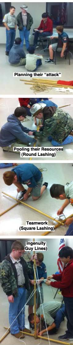
When the patrols have learned their round lashing and square lashing, they’ll be ready for this indoor challenge which gives them an opportunity to use what they’ve learned in a new way. Additionally, they get to plan their “attack,” pool their resources, use their ingenuity, and put into practice the teamworking skills necessary to complete the task.
Materials needed for each patrol:
six 5-foot Scout Staves
seven 6 to 10-foot x 1/4-inch manila lashing ropes
four light guylines
one 15-foot light line (for halyard)
one 3-foot cord (to make top loop for halyard)
two pencil-sized sticks (if needed to secure patrol flag to halyard through existing grommets)
their patrol flag
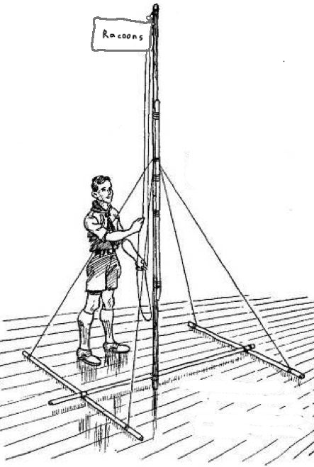
The challenge. Ask the patrols to each build a self-standing flagpole capable of raising and lowering their patrol flag. Have the necessary materials on hand, and present them with the following design:
NOTE: This challenge can be presented without the design! If no design is provided, and just the challenge is given as stated above, the Scouts will be confronted with having to figure out their own approach that will work! However, the design is ingenious and sooner or later worthy of being shared.
Some thoughts:
1) This self-standing flagpole is ideal when a flagpole is desired indoors (or outdoors when there’s no way to drive stakes into the ground or dig a hole).
Set a time limit and make it a race.
2) Depending on the ceiling’s height, the flagpole can be built higher merely by lashing on additional pole sections.
3) To shorten the pole if the ceiling is lower than 10 feet, just round lash two staves together.
4) Naturally, following the design, the Patrol Leader can have members of his patrol divide the tasks so that the pole and the support frame are constructed simultaneously.
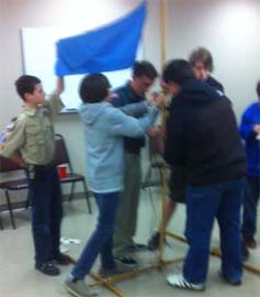
Got it up!
5) The method of placing two 5-foot staves end to end, and lashing a third joining stave in the middle where the two others touch can be seen as somewhat of a departure, but will yield a very stable 10-foot flagpole, provided the four Round Lashings are tight and well-spaced.
6) The 3′ cord for the halyard loop can be fastened to the top stave in a variety of ways: a bowline with a clove hitch, a bowline with two half hitches, a doubled over rolling hitch, etc., etc.
7) The guylines can also be attached in a variety of ways (and will be), though rolling hitches around both the pole and the support frame are recommended.
Please refer to the “sales pitch” provided in the Tool Rack post spelling out all the advantages inherent in building one of these simple camp gadgets. It is a good-looking campsite improvement project, but mainly, it’s got major functionality.
The main difference between this version and the other is with the first tool rack, all the tools are hung, suspended by a cord from the upper cross piece and are supported by resting against the lower cross piece. In this tool rack, the tools’ handles are slipped in between two parallel cross pieces. This way, they’re held very nicely in place, and any shifting or wobbling around, often experienced in the first rack, is eliminated.
The two racks are also constructed in like manner, again refer back to the Tool Rack post. No need repeating it here. However, in this version, the diameter of the two 6-foot uprights need to be a little larger than the diameter of the thickest handle of any tool you’ll be hanging.
Parallel Square Lashings
When you’re ready to lash on the cross pieces, lash on the first higher than the longest tool. It needs to be at a height easy enough to comfortably place the tools on and take the tools off the rack, without needing to reach up too high or bend over. Secure the first cross piece in front of the uprights with a couple of tight square lashings, and then secure the second cross piece to the uprights in exactly the same position, but on the other side of the uprights. You’ll be tying a tight square lashing here too, and there’s plenty of room to wrap and frap. That’s all there is to it.
By the way, if you’d like to erect a cover over the tool rack, lash another cross piece to the very top, and rig up a tarp, using this third cross piece as a ridge pole.
Protecting the tools from rain and providing a covered area for storage.